The Review of Material Test Certificates which is also known as Material Test Report (MTR) is crucial to ensure the quality of materials used in oil and gas fabrication. All raw materials used in the Oil and Gas industry, such as pipes, fittings, flanges, and plates, must have a valid Material Test Certificate (MTC) provided by the manufacturer.
The inspection engineer is responsible for confirming that the material’s test certificate aligns with the requirements specified in the applicable material standards, specifications, and purchase order.
In this article, you’ll learn how to read and review the Mill Test Report during the shop and inward material inspection.
Reviewing the MTC involves several steps, including material identification and traceability check, chemical composition analysis, assessment of mechanical properties, evaluation of non-destructive testing (NDT) results, review of heat treatment information, examination of dimensions and tolerances, and consideration of non-technical information such as the manufacturer’s name and address, purchase order number, and date.
For this article, I’ve chosen the Seamless Pipe Material Test Certificate as an example. From now on, I’ll refer to the Material Test Certificate as MTC, MTR, or TC for simplicity. Here’s a sample MTC for a seamless pipe.
I’ve numbered each step to make it easier to follow. You can download the full mill test certificate from this link – Sample Material Test Certificate of Seamless Pipe.
Review Material Test Report and Type of Certificate
Step 1 – Type of Material Certificate
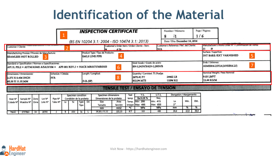
The first thing you’ll notice on the certificate is the type of inspection certificate. In this case, you can see that this TC is issued in accordance with BS EN 10204 3.1, the 2004 edition, or its ISO version 10474 3.1, the 2013 edition. This standard defines the types of inspection documents for metallic products.
The standard outlines different types of certificates, each representing varying levels of inspection and documentation. Common types include Type 2.1, Type 2.2, Type 3.1, and Type 3.2. It’s crucial to verify that the certificate type matches the required level of inspection for your specific application.
Here, 3.1 indicates the type of inspection document. Other types include 2.1, 2.2, and 3.2.
Certificate type 2.1 is a Declaration of Compliance with the order, while 3.2 is a Test Report issued by both the manufacturer’s authorized inspection representative, independent of the manufacturing department, and an independent inspector.
I’ll explain this in more detail in the upcoming video.
For this video, 3.1 means these pipes have been inspected by the manufacturer’s inspection department, which operates independently of the production department. The material meets all the quality requirements specified in the purchase order.
So, this field will provide you with the level of inspection conducted on the material.
Piping Component Quiz – Test yourself, Take This Quiz
Step 2- The Administrative Information
I have highlighted this section, which contains information such as the customer’s name, order number, and the manufacturer’s internal work order. These details will help you correlate this TC with your purchase order.
Step 3 – The Manufacturing Process
This field is the first technical detail you need to check. Material manufacturers can use different methods of manufacturing, and ASME and ASTM material specifications specify the acceptable methods for specific material grades.
For example, seamless pipes can be manufactured using methods such as hot rolled, cold rolled, or forging. In this sample MTR our seamless pipes are manufactured using the hot-rolled method.
So, check this and confirm with your material grade. If you are checking pipe fittings, they can be wrought or forged, and the same goes for other products.
Step 4 – The Product Type
The pipe can be seamless, ERW, spiral wound, or LSAW welded pipe. The type of pipe offered for inspection is mentioned here. In our sample TC, it is a seamless pipe.
For pipe fittings, it can be an elbow, tee, reducer, or other types depending on the order.
Step 5 – The Surface Condition of the Product
Steel products such as pipes and fittings can be supplied with external surfaces painted, galvanized, or bare. Most manufacturers will supply these products with just a rust-preventive varnish coating, as is the case here.
The final painting will be done on-site. Typically, there is no internal painting required for carbon steel materials used in process piping. However, galvanized pipes are also used for some utility services.
The surface condition of the product depends on the requirements of the purchase order. So, you can confirm this with the order requirements.
Step 6 – The Standards and Specifications of the Material.
The Mill Test Report should indicate the relevant standards that the product complies with, such as API, ASME, ASTM, NACE, and others. This ensures that the material meets the required product specifications and quality standards, and that the product has been produced and tested according to recognized industry standards.
In our sample TC, the pipes meet multiple standards such as API 5L PSL2, ASTM A53 and A106, ASME SA53 and SA106. I am not aware of AFP. If you know it, mention it in the comments.
These pipes also meet NACE MR0175 and MR0103 requirements. NACE standards certify that the product can withstand corrosive environments.
Unlock New Skills with Our Best Selling Online Courses
Step 7 – The End Type of the Product
The end type of the product, either plain ends or beveled ends, is specified here. Depending on the welding requirements, you can specify the end types. Usually, small bore and less thick pipes come with plain ends, while for higher thickness, J-type or V-type ends can be used.
Before we move on to the next part of the video, if you want to advance your career in the oil and gas industry and gain practical knowledge from industry experts, you can check out our comprehensive online courses on my website, hardhatengineer.com. Click the link in the description to enroll today and accelerate your learning journey.
Step 8 – The Dimension Information of the Seamless Pipe
The MTR should include key material dimensions such as length, diameter, thickness, or any other relevant measurements. Verifying these dimensions ensures that the material accurately matches your project requirements.
Here, the first detail mentioned is the size of the pipe, which can be stated in millimeters (as in this case) or inches. The second detail is related to the schedule number of the pipe, specifying the thickness. However, it is marked as “not applicable” here. Can you guess why?
That’s because the thickness of the pipe is mentioned along with the pipe size. The next field mentions the length of the pipe. “D R” means double random.
During production, pipes are not manufactured in the same lengths, and during the construction of process plants, varying lengths of pipes are required. To address this issue, standards have defined pipe lengths in single random and double random categories.
Single random pipes are shorter in length and typically range from 4.8 to 6.7 meters. However, in a given lot, 5% of the pipes can have lengths between 3.7 and 4.8 meters. Pipes shorter than this specified range are not acceptable.
On the other hand, double random pipes are longer in length. The entire lot must have a minimum average length of 10.7 meters, and the shortest pipe cannot be shorter than 4.8 meters. Additionally, within the lot, 5% of the pipes can have lengths ranging from 4.8 meters to 10.7 meters.
The next field indicates the quantity of pipes offered for inspection in the current lot. Finally, the last field in the dimension block represents the nominal weight of the pipe, measured in kilograms per meter.
Review of Material test certificates is a long and time taking task at the beginning. But once you get the experience, it will be much easier and faster.
Review Mechanical Testing Result
Step 9 – Verify the Mechanical Test Results.
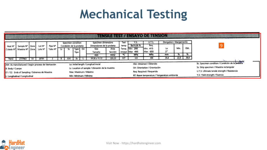
The material certificate should provide details of the key mechanical tests conducted on the material, such as tensile strength, yield strength, and elongation. Reviewing these results ensures that the material meets the required mechanical properties for its intended application.
Let’s go through the details provided in each column. The first column is the heat number of the material. The heat number is a unique identification number assigned to each batch or lot of material during manufacturing.
By referencing the material heat number, manufacturers, suppliers, and customers can access detailed records or certificates that provide information about the material’s composition, properties, and production history.
After the heat number, a sample number is given. It is used to track the sample in the lab. The next column, “zone,” indicates the location from which the sample was taken (end one or end two). Refer to the explanation provided for each shortcode used in the table to understand these references.
The following column shows the lot number of the pipe. One heat number can have multiple lot numbers, indicating that the pipes with these lot numbers were manufactured in the same batch.
The “specimen condition” column indicates the location and condition of the sample. In this case, “LS” refers to the location of the sample, where “B” indicates that the sample is taken from the pipe body. “SC” denotes the specimen condition, and “AM” means “As Manufactured,” indicating that no additional treatment has been given to the sample, and it is directly cut from the pipe.
For mechanical testing, the sample can be a rounded bar or a flat metal strip. Here, it is mentioned that the sample type is a strip cut from the pipe body.
The last column in this section indicates the orientation from which the sample was cut from the pipe. “L” indicates the longitudinal direction. You can see the location of the sample in the pipe shown here.
Let’s move on to the next column, which displays the dimensions of the sample, including length, width, and area. Once the sample is cut from the pipe, it is machined to the dimensions specified by the testing standard before conducting destructive testing.
The following column indicates the testing temperature. “RT” means room temperature. Please note that depending on the material’s service conditions, the testing temperature can be sub-zero or higher than room temperature.
The remaining columns show the results of the mechanical tests. “YS” refers to yield strength, with the minimum and maximum acceptable values for the material grade and the obtained result mentioned in the first column. Following yield strength, “UTS” indicates ultimate tensile strength, with the same format of minimum and maximum values alongside the obtained result. The unit for both yield strength and ultimate tensile strength is megapascals (MPa).
The last three columns display the results of the elongation test, including the initial length of the sample in millimeters, the minimum acceptable percentage, and the obtained result.
It is crucial to cross-check the minimum and maximum values of all these test results with the applicable material standards. In this case, the standards are A106, API 5L, and A53.
Chemical Test Result Review in Material Test Certificates
Step 10 – Verifying the Chemical Test Results
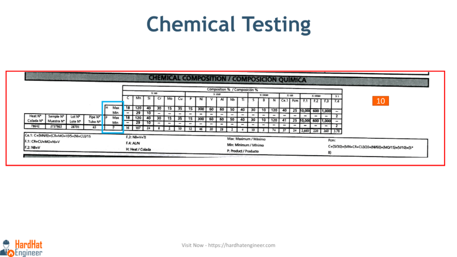
In this table, the first four columns are related to the identification of the sample, as discussed earlier.
The Material Test Report should outline the chemical analysis of the material, specifying the minimum and maximum acceptable levels of each alloying element. In the blue box, you can see the minimum and maximum values provided for the material grade.
“H” indicates the value given in the heat number, while “P” represents the result obtained in the product testing. The table displays various alloying elements and their percentages. You may be wondering why these percentages add up to more than 100%. Well, if you look at the top row, you’ll see the “x time multiplication” mentioned.
For example, the value of carbon is 18 divided by 100, which equals 0.18. Similarly, the value of phosphorus is 15 divided by 1000, and so on.
“CE” represents the carbon equivalent of the steel. There are different formulas to calculate CE, and the formula used here is provided in the note below. “PCM” is used to measure crack susceptibility, and you can refer to the formula given to calculate the crack susceptibility factor, which involves more alloying elements than the carbon equivalent.
“F1,” “F2,” “F3,” and “F4” are other factors used to measure the remaining alloying elements, and the formulas for each of these factors are also provided.
To determine acceptable values, refer to the material standards.
Review Hardness Test Details in MTR
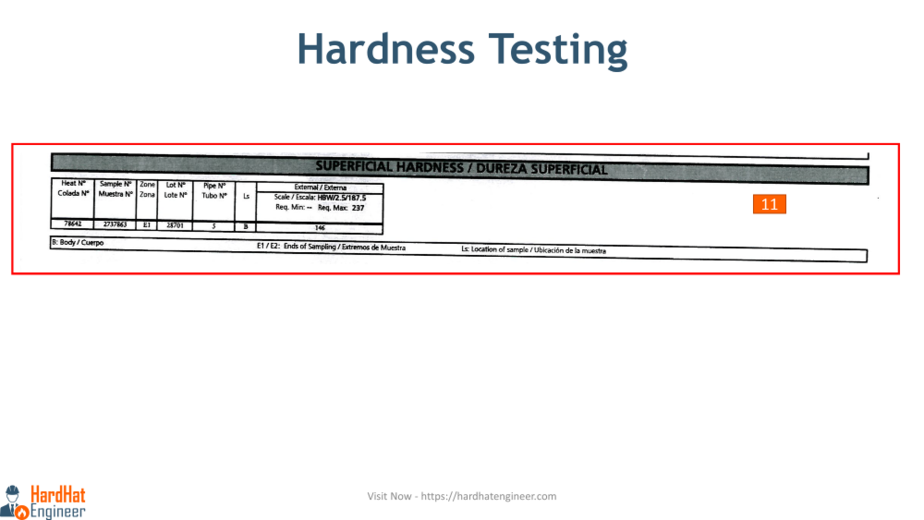
Step 11 – Verifying the Hardness Test Results
After checking the mechanical and chemical test results, you need to examine the surface hardness of the pipe. In this case, the HBW 2.5 with a 187.5 scale is used, which means a Brinell 2.5 mm tungsten carbide ball is used with a 187.5 kilogram force load for testing.
The maximum acceptable value is 237 BHN (Brinell Hardness Number), and the result obtained is 146 BHN.
Are You Piping Components Master?
Bend Test, Hydro Test, and Heat Treatment Records Check in MTC
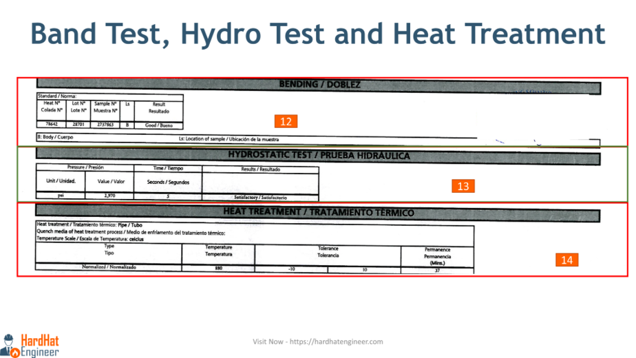
Step 12 – Check the Bend Test Result
Bend tests are conducted to assess the material’s ductility and resistance to cracking. The result is determined through visual examination. If any cracks are observed in the bend area, the sample will not be accepted.

Step 13 – Confirm the Hydro Test Result.
The unit of pressure testing is PSI (pounds per square inch), and the test pressure is 2,970 PSI. The holding time is only 5 seconds, and the result is acceptable. The pressure requirements are calculated based on the pipe’s thickness, and the holding time value is specified in the applicable pipe standards.
Step 14 – Heat Treatment Details
Here, the pipes are normalized at 880 degrees Celsius for a holding time of 37 minutes. The heat treatment requirements depend on the material standards, pipe thickness, and manufacturing methods.
Special and Supplementary Requirements in Material Certificate
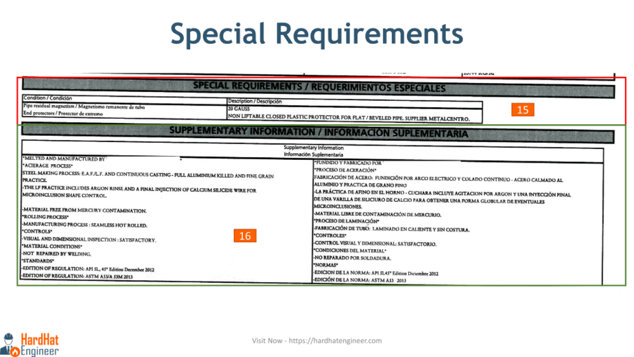
Step 15 – Special Requirements
If any special requirements are specified in the purchase order, as in this case, they are checked in Step 15. Here, two special requirements are mentioned: one related to residual magnetism and the other related to end protection using a plastic cap.
Step 16 – Supplementary Requirements
Next, certain supplementary requirements need to be checked according to the standard and good practice. Let’s see some of them in Step 16.
Here, the steel manufacturing method, mercury contamination, and gas removal methods are mentioned. Additionally, pipe rolling, visual and dimensional inspection status, and welding repair status are mentioned.
The last piece of information is the edition of the standards used to certify the pipe, which is also stated. It’s important to check the material using the current edition of the standards mentioned in the Material Test Certificate, as requirements may change with different editions.
Non-Destructive Testing
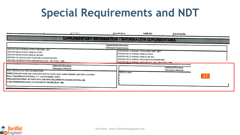
Step 17 – The Non-Destructive Testing (NDT)
In the image given above, you can see the list of NDT carried out during the manufacturing of the pipe. For the pipe body, Electro-Magnetic Inspection (EMI) has been conducted to check for cracks or pitting defects. In addition to EMI, Magnetic Particle Testing is also performed on the pipe ends to identify defects in the beveled face of the pipe.
The next detail mentioned is the temperature of the pipe during the entire manufacturing process before it is allowed to cool in still air.
Marking Requirements Checks
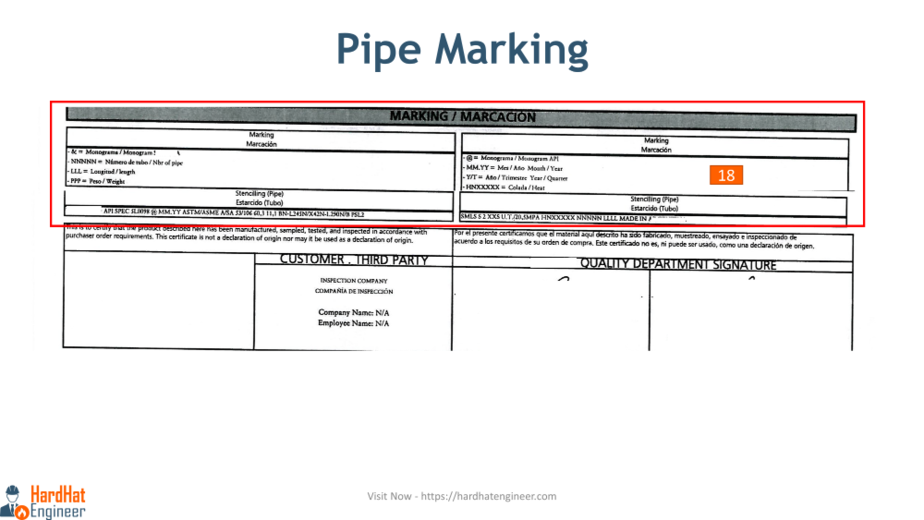
Step 18 – Check the Marking Details on the Product.
Here, you can see that manufacturing standards such as API, ASTM, ASME, material grade, pipe size, thickness (schedule number), length, heat number, etc., are marked on the pipe using the stenciling method.
By following this step-by-step method, you can review the Material Test Certificate of any product.

