In this article, I am going to discuss the Centrifugal Pump Diagram. I will show you various centrifugal pumps with a schematic and cross-section to show you the different parts inside. I have covered the following centrifugal pump diagram with parts.
- Single stage open impeller pump
- Single stage closed impeller pump
- Multistage Pump
- Single stage double suction centrifugal Pump
- Schematic drawing of centrifugal Pump
Centrifugal pump comes in different designs to suit the end user’s need. The simplest and regularly used type is a single stage. An open impeller design is used when the liquids have some solid particles. If you want to learn about different types of pumps, check this earlier article on the types of pumps used in a process plant.
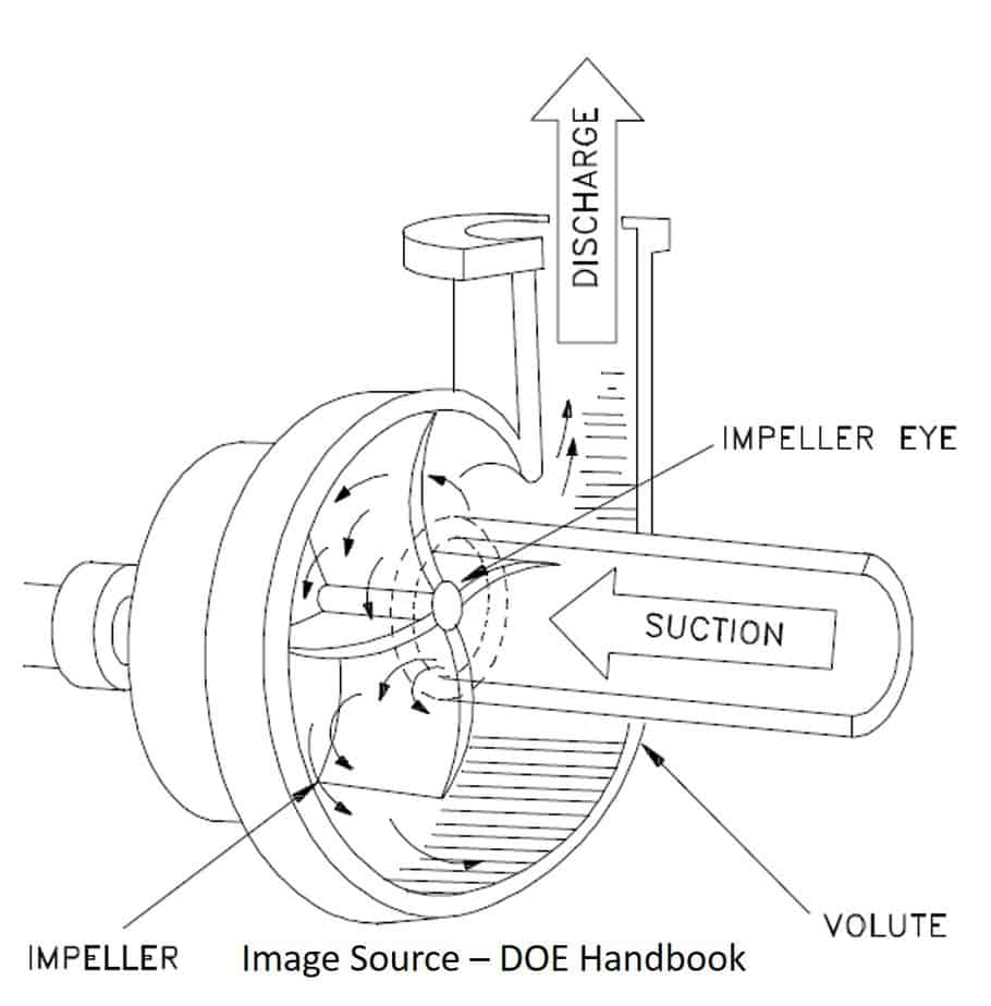
Single Stage Open Impeller Centrifugal Pump Diagram
The image below shows the cut section of the single-stage pump with an open impeller design. This is the simplest diagram of the pump, which shows only major parts such as the body, impeller, and suction–discharge flanges.
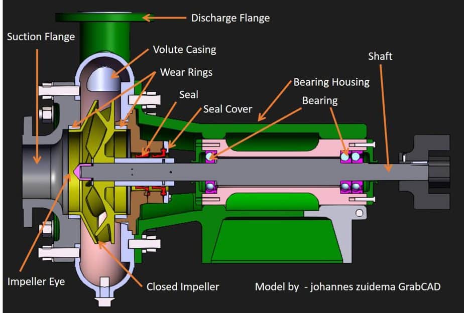
Single Stage Closed Impeller Pump Schematic
The image shown here is the single stage, closed impeller centrifugal pump schematic diagram. This is a typical pump cross-section. You can see the various parts marked.
Centrifugal Pump Quiz – Test yourself, Take This Quiz
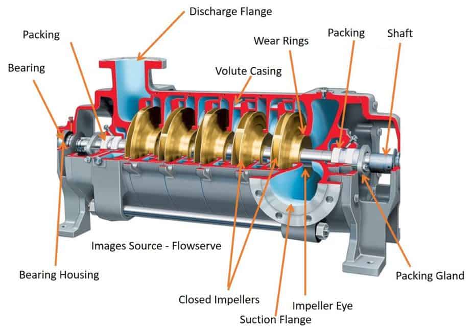
Multistage Closed Impeller Pump Cross Section
The image shown here is a multistage between the bearing pump. This type of pump is used when you want very high discharge pressure. Each stage will increase the pressure. Each impeller is connected in series so that discharge of the first stage will become suction of the next stage. This pump is not suitable for high volume discharge.
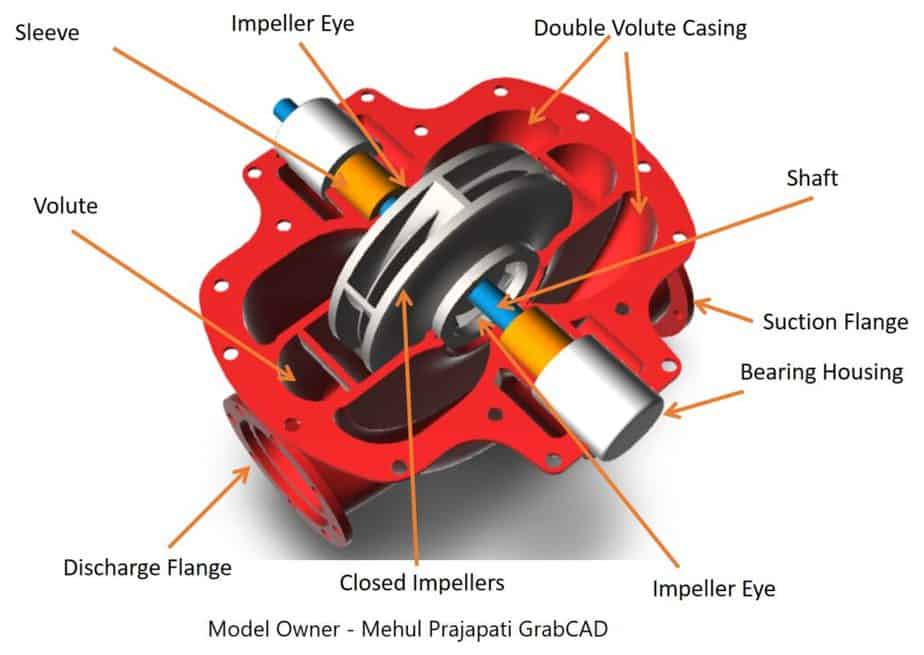
Single Stage Double Suction Centrifugal Pump
On this slide, you can see the single stage double suction centrifugal pump. What is special about this pump is the casing and impeller design. If you look at this suction flange, you can see that it is splitting the liquid into two halves. The impeller of this type of pump is designed in such a way that liquid can enter from both sides. On the impeller, you can see two exit channels. It looks like two closed impellers attached together.
Liquid from the impeller enters the volute that directs it toward the discharge flange.
In this last part of this topic, I want to show you real-life pump drawings used in shops and fields.
Schematic Drawing of Centrifugal Pump
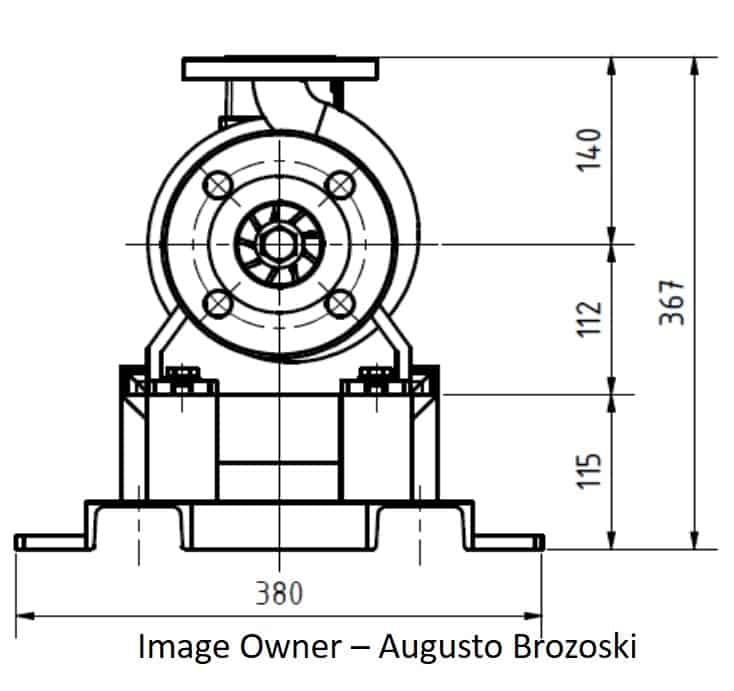
The first drawing is a general arrangement drawing of a pump. This drawing is the property of Mr. Augusto Brozoski. He teaches 3D Model design. You can check his YouTube video to learn how to draw this model. The link is given in the description.
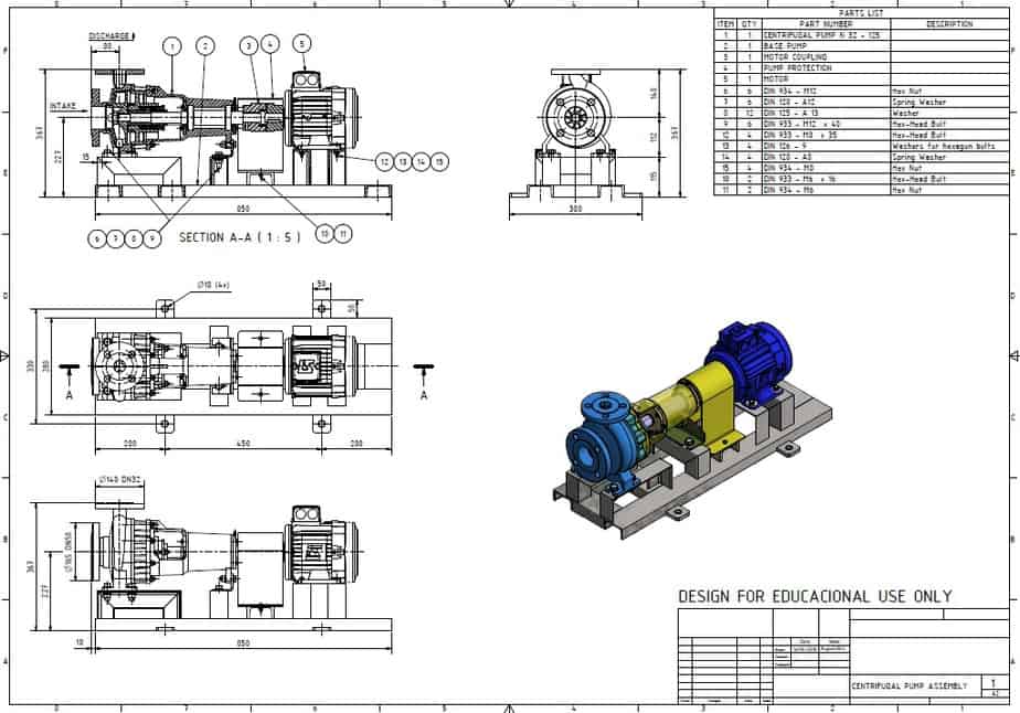
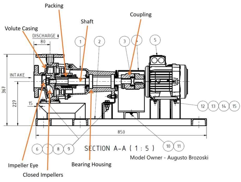
This Schematic drawing of the centrifugal Pump shows five different views of a pump. This image is cross section view of only the pump section. In this view, you can see the pump’s internal parts, such as the impeller, impeller eye, packing, shaft, etc.
The number shows only the main components such as the pump body, motor, coupling, support frame, and nut bolts. You can see the part name against each number in the table given here. I will explain to you about each of these parts in more detail in upcoming videos on pump parts.
The cross-section view shown below will explain to you more about the pump. The number shows only the main components such as pump, motor, coupling, support frame, and nut bolts. You can see other parts that I have marked, such as the end suction nozzle, impeller, impeller eye, shaft, gland packing, and bearing housing.
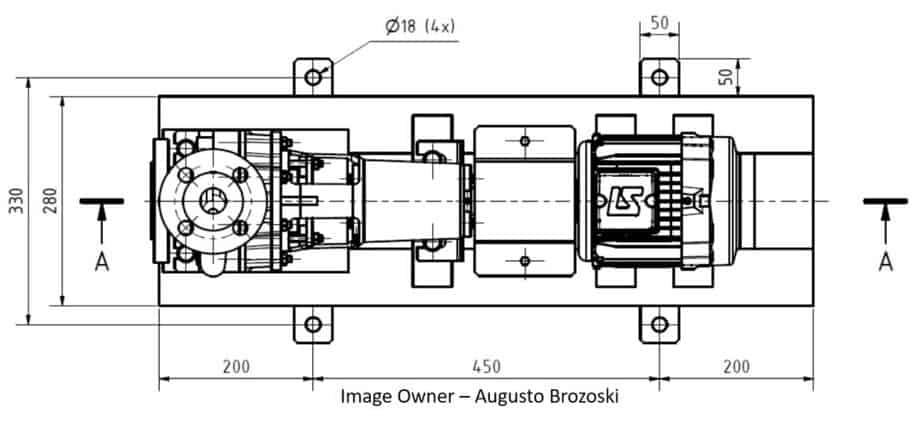
This second view is a top view of the pump. In this view, you can see the frame’s dimensions and the centerline distance of the discharge nozzle.
The third view is again a side view but without cross-section. In this view, you can see the elevation of the suction nozzle from the base.
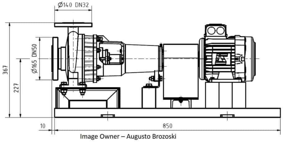
The fourth view is an end view. In this view, you can see the height of the discharge nozzle.
The last is the 3D view of the final pump model.
This drawing is used in the shop fabrication and on-site to get various pump dimensions. This is all about centrifugal pump schematic drawing. If you want to learn more about a pump, please check the full course on the same. This course has more than 7 hours of content on the pump.
Are You Piping Components Master?


