Color coding of pipelines and piping materials are standard industry practices. Color marking will make identification easier for raw material and fluid that is being transported by the pipe. There are various national and international Pipe Color Code Standards available. (I have used both British and American versions to spell color/colour)
- ASME/ANSI A13.1 – Scheme for the Identification of Piping Systems
- BS 1710 – Specification for Identification of Pipelines and Services
- IS 2379 – Pipelines Identification Colour Code
- PFI ES-22 – Recommended Practice for Color Coding of Piping Materials
Color Coding of Piping Material – PFI ES-22
Why the color coding of piping material?
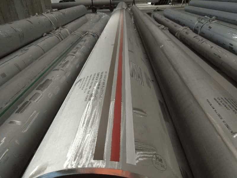
Various grades of carbon steel, alloy steel, and stainless steel are used during construction and fabrication. To avoid mixing of this material and easy storing and retrieving in the warehouse, piping components such as pipe, fittings, flanges, and valves are color coded.
Most companies have their own color coding system. Pipe Fabrication Institute (PFI) Standard ES-22 provides Piping Materials color coding requirements for the most commonly used piping material grades. It also provides guidance on marking location of piping components.
Refer to below images for the color band location on piping components.
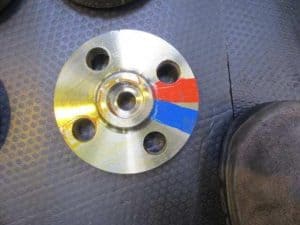
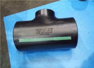
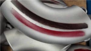
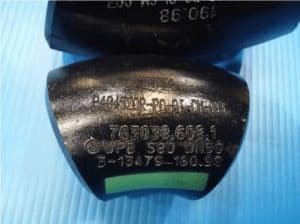
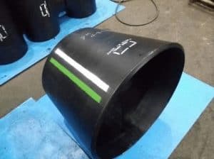
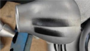
Color Code for Pipe Material Identification – PFI Standard ES-22 -1999
Carbon Steel Material
| Carbon Steel | ||
|---|---|---|
| Material | Material Garde | Band / Strip Color |
| Carbon Steel, Electric Resistance Welded Pipe | A53 Gr. B/API | 1 solid white |
| Carbon Steel, Smls, specified tensile strength under 70,000 psi (483 MPA) | A53 Gr. B | No Marking |
| Carbon Steel, killed steel | A106 Gr. B | 1 solid green |
| Carbon Steel, specified tensile strength 70,000 psi (483 MPA) and over | A106 Gr. C | 2 solid green |
| Carbon Steel, low temperature (impact tested) | A333 Gr. 6 | 1 solid red |
Piping Component Quiz – Test yourself, Take This Quiz
Unlock New Skills with Our Best Selling Online Courses
High Yield Carbon Steel
| High Yield Carbon Steel | ||
|---|---|---|
| Material | Material Garde | Band / Strip Color |
| 52,000 min. yield | API 5L X-52 | 1 solid yellow, 1 solid green |
| 60,000 min. yield | API 5L X-60 | 1 solid yellow, 1 solid pink |
| 65,000 min. yield | API 5L X-65 | 2 solid yellow |
| 70,000 min. yield | API 5L X-70 | 1 solid yellow, 1 solid orange |
Low Alloy Materials
| Low Alloy Materials | ||
|---|---|---|
| Material | Material Garde | Band / Strip Color |
| C-Mo steel | A335 Gr. P1 | 1 solid orange |
| 1 Cr-1/2 Mo Steel | A335 Gr. P12 | 1 solid orange, 1 solid blue |
| 1 1 /4 Cr-1/2 Mo Steel | A335 Gr. P11 | 1 solid yellow |
| 2 1/4 Cr-1 Mo Steel | A335 Gr. P22 | 1 solid blue |
| 5 Cr-1/2 Mo Steel | A335 Gr. P5 | 1 solid blue, 1 solid yellow |
| 9 Cr-1/2 Mo Steel | A335 Gr. P9 | 2 solid orange |
Ferritic and Martensitic Stainless Steels
| Ferritic and Martensitic Stainless Steels | ||
|---|---|---|
| Material | Material Garde | Band / Strip Color |
| Type 405 | A268 TP405 | 1 solid green, 1 solid black |
| Type 410 | A268 TP410 | 1 solid green, 1 solid red |
Austenitic Stainless Steels
| Austenitic Stainless Steels | ||
|---|---|---|
| Material | Material Garde | Band / Strip Color |
| Type 304 | A312 TP304 | 1 solid black |
| Type 304L | A312 TP304L | 2 solid black |
| Type 304H | A312 TP304H | 1 intermittent black |
| Type 309 | A358 Gr309 | 1 solid black, 1 solid brown |
| Type 310 | A358Gr310 | 1 solid green, 1 solid orange |
| Type 316 | A312 TP316 | 1 solid gray |
| Type 316L | A312 TP316L | 2 solid gray |
| Type 316H | A312 TP316H | 1 intermittent gray |
| Type 317 | A312 TP317 | 1 solid brown, 1 solid green |
| Type317L | A312 TP317L | 1 solid brown, 1 solid red |
| Type 321 | A312 TP321 | 1 solid pink |
| Type 321 H | A312 TP321H | 2 solid pink |
| Type 347 | A312 TP347 | 1 solid brown |
| Type 347H | A312 TP347H | 2 solid brown |
Unlock New Skills with Our Best Selling Online Courses
Nickel Based Alloys
| Nickel Based Alloys | |
|---|---|
| Material | Band / Strip Color |
| Nickel 200 | 1 solid black, 1 solid pink |
| Incoloy 800 | 1 solid black, 1 solid orange |
| Incoloy 800H | 1 solid gray, 1 solid red |
| Incoloy 825 | 1 solid gray, 1 solid blue |
| Inconel 600 | 2 solid blue |
| Inconel 625 | 1 solid blue, 1 solid pink |
| Hastelloy Alloy 8-2 | 1 solid red, 1 solid orange |
| Hastelloy Alloy C-276 | 1 solid red, 1 solid blue |
| Hastelloy Alloy C-22 | 2 solid red |
| Hastelloy Alloy G | 1 solid red, 1 solid yellow |
| Carpenter Alloy 20 C 8-3 | 1 solid black, 1 solid blue |
| Monel 400 | 1 solid black, 1 solid yellow |
Color Coding of Pipeline and Piping Identification
Oil and Gas Industries, Process industries are complex installations. Piping systems are used in these plants to transport various fluids. These pipelines transport various industrial materials such as gases such as Air, Nitrogen, Oxygen, Hydrogen, etc., liquids such as water, acids, hydrocarbon, toxic materials, etc.
Identifying the material pipeline transporting without a proper pipe color code is extremely difficult. Systematic color coding of pipelines and piping systems is essential to reduce the safety hazard and the possibility of mistakes in identification and accidents associated with the wrong identification of pipelines during an emergency situation. Uniformity of color marking promotes greater safety, lessens the chances of error, and reduces hazards in handling material inside the pipelines.
National and international standards provide the guidelines for uniform color coding in industries that are used to color code of pipes to identify.
- ASME A13.1 – Scheme for the Identification of Piping Systems
- BS 1710 – Specification for Identification of Pipelines and Services
- IS 2379 – Pipelines Identification Colour Code
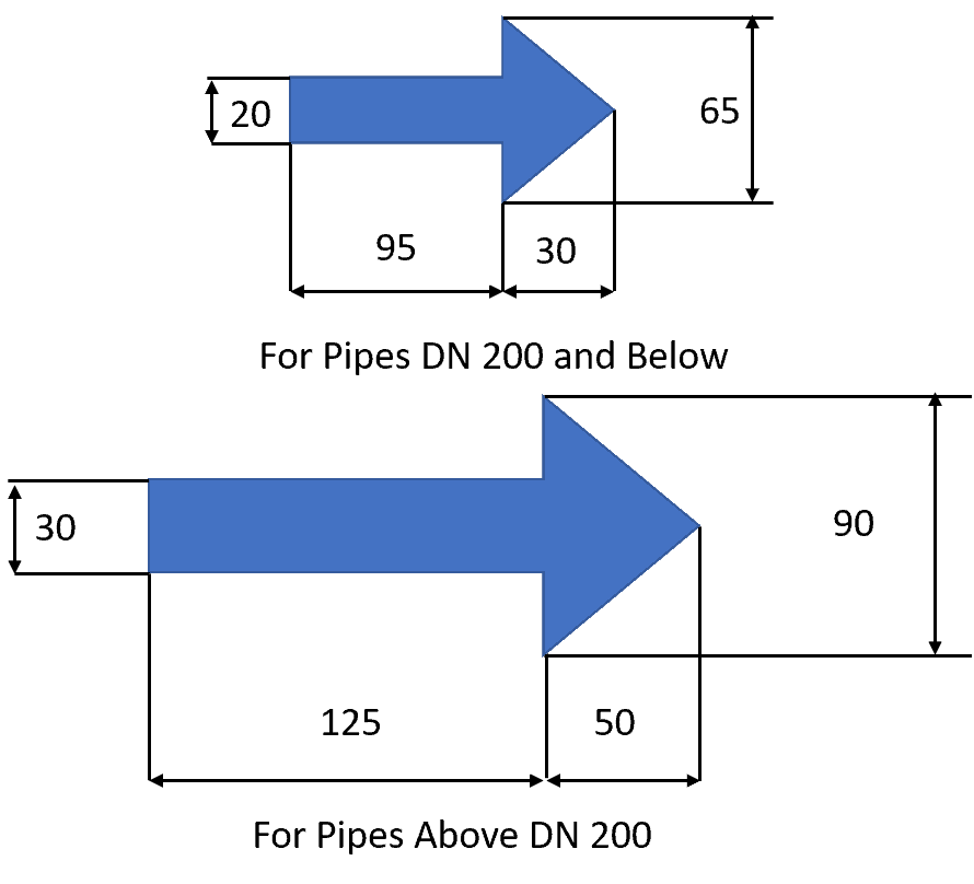
These standard uses different color code methodology to identify the pipe material. They use a base color, band color, letters, and direction arrow to identify fluid inside the pipeline.
ANSI/ASME A13.1 – Scheme for the Identification of Piping Systems
The purpose of the ASME/ANSI A13.1 Standard is to establish a common system that assists in the identification of hazardous materials conveyed in piping systems and their hazards when released into the environment.
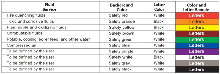
ASME A13.1 – 2015 edition has six fixed colors, and four users define colors that can be used to identify hazardous material. In this standard, the following categories are used;
- Flammable – Fluids or vapor or produce vapors that can be ignited and continue to burn in air.
- Combustible – Fluids that can burn, but are not flammable.
- Oxidizing – Oxidizing fluid is any gas or liquid that may, generally by providing oxygen, cause or contribute to the combustion of other material more than air does.
- Toxic and Corrosive – Fluids that are corrosive or toxic, or will produce corrosive or toxic substances when released.
- Fire Quenching – Fluid Such as water, foam, and CO2 used in sprinkler systems and firefighting piping systems.
Size of Label and Letters as per ASME B13.1-2015
| Outside Diameter of Pipe in Inches | Outside Diameter of Pipe in mm | Length of Color Field, A, in Inches | Length of Color Field, A, in mm | Size of Letters, B, in Inches | Size of Letters, B, in mm |
|---|---|---|---|---|---|
| 3⁄4 to 11⁄4 | 19 to 32 | 8 | 200 | 1⁄2 | 13 |
| 11⁄2 to 2 | 38 to 51 | 8 | 200 | 3⁄4 | 19 |
| 21⁄2 to 6 | 64 to 150 | 12 | 300 | 11⁄4 | 32 |
| 8 to 10 | 200 to 250 | 24 | 600 | 21⁄2 | 64 |
| Over 10 | over 250 | 32 | 800 | 31⁄2 | 89 |
BS 1710 – Specification for Identification of Pipelines and Services
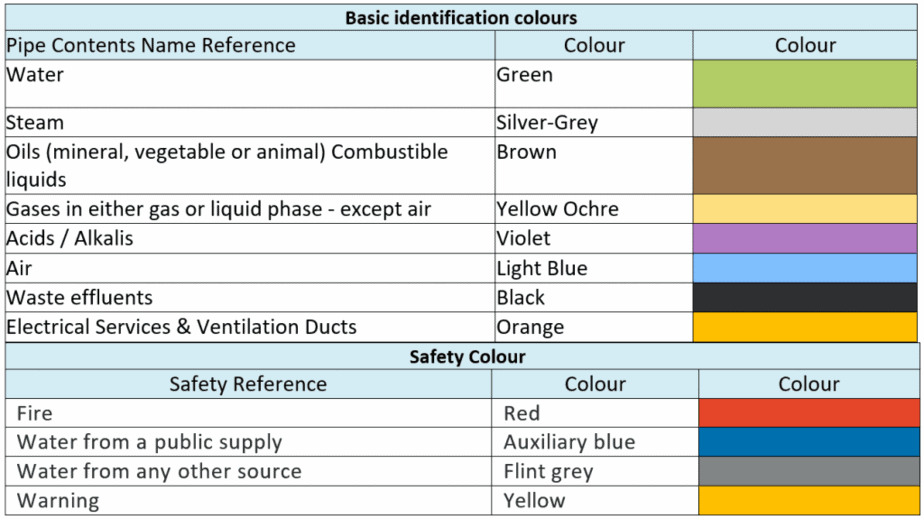
BS1710 uses two types of colour coding to identify the content of pipe and hazard.
- Base colour – Base colours are used to indicate the content inside the pipe.
- Safety colours – These colours are used as band colours that applied in conjunction with the base pipe color code to create various service identifiers.
Other than colour code, additional information regarding the nature of the contents of the pipe by using the following systems either individually or in combination:
- Name in full
- Abbreviation of name
- Chemical symbol and
- Appropriate code indications or code colour bands
Size of Label as per BS 1710 -2014
- When Only Basic Identification Color Used
| Pipe Diameter | Minimum Band Width |
|---|---|
| Up to 50 mm | 130 mm |
| 50 mm to 100 mm | 275 mm |
| above 100 mm | 450 mm |
Unlock New Skills with Our Best Selling Online Courses
2. Basic identification
| Pipe Diameter | Minimum Band Width – Basic Colour (1) | Minimum Band Width – Safety Colour (2) |
|---|---|---|
| Up to 50 mm | 50 mm | 30 mm |
| 50 mm to 100 mm | 100 mm | 75 mm |
| above 100 mm | 150 mm | 150 mm |
IS 2379 – Pipelines Identification Colour Code
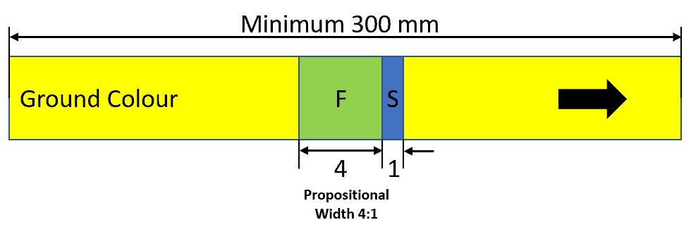
IS 2379 is Indian Standard for the colour coding requirements. It is quite comprehensive and a little complex as compared to BS and ASME standards. IS 2379 is more in line with BS 1710. It used the ground colour, band colour, and letter labeling to identify fluid content and associated hazards.
This standard covers piping systems that include pipes of any kind and in addition fittings, valves, and pipe coverings. Supports, brackets, or other accessories are excluded from this standard. This standard is not applicable to pipelines buried underground or used for electrical services.
Refer to the table for the ground colour that used in pipeline marking.
| Ground Colours | |
|---|---|
| Substance | Colour |
| Water | Sea green |
| Steam | Aluminium to IS 2339 |
| Mineral, vegetable, and animal oils, combustible liquids | Light brown |
| Acids | Dark violet |
| Air | Sky blue |
| Gases | Canary yellow |
| Alkalies | Smoke grey |
| Other liquids/gases which do not need identification | Black |
| Hydrocarbons/organic compounds | Dark admirality grey |
Size of Label and Letters as per IS 2379 – 1990 (Reaffirmed 2006)
| Length of the Colour Band | |||
|---|---|---|---|
| Nominal Pipe Size (mm) | Ground Colour | First Colour Band (mm) | Second Colour Band |
| 80 NB and below | Throughout the entire length or Band no case less than 300 mm | 25 | 4:1 Proportion to the First Colour Band |
| Letter Size | |
|---|---|
| Outside Diameter of Pipe (mm) | Size of Legend (mm) |
| 20 to 30 | 10 |
| Above 30 to 50 | 20 |
| Above 50 to 80 | 30 |
| Above 80 to 150 | 40 |
| Above 150 to 250 | 90 |
| Over 250 | 90 |
Commonly used Pipe Color Code As per Is 2379
| Pipe Colour Code Use in Refinery As per IS 2379 | |||
|---|---|---|---|
| Contents | Ground Colour | First Colour Band | Second Colour Band |
| Cooling Water | Sea green | French blue | – |
| Boiler feed water | Sea green | Gulf red | – |
| Drinking water | Sea green | French blue | Signal red |
| Plant air | Sky blue | Silver grey | – |
| Very high pressure steam | Aluminium to IS 2339 | Signal red | – |
| High pressure steam | Aluminium to IS 2339 | French blue | – |
| Medium pressure steam | Aluminium to IS 2339 | Gulf red | – |
| Low pressure steam | Aluminium to IS 2339 | Canary yellow | – |
| Light diesel fuel | Light brown | Brilliant green | – |
| Lubricating oil | Light brown | Light grey | – |
| Flare gases | Canary yellow | – | – |
| Nitrogen | Canary yellow | Black | – |
| Oxygen | Canary yellow | White | – |
| Hydrogen | Canary yellow | Signal red | French blue |
| Naptha | Dark Admirality grey | Light brown | Black |
| LPG (Liquid) | Dark Admirality grey | Brilliant green | Dark violet |
Location of the color band and Labels
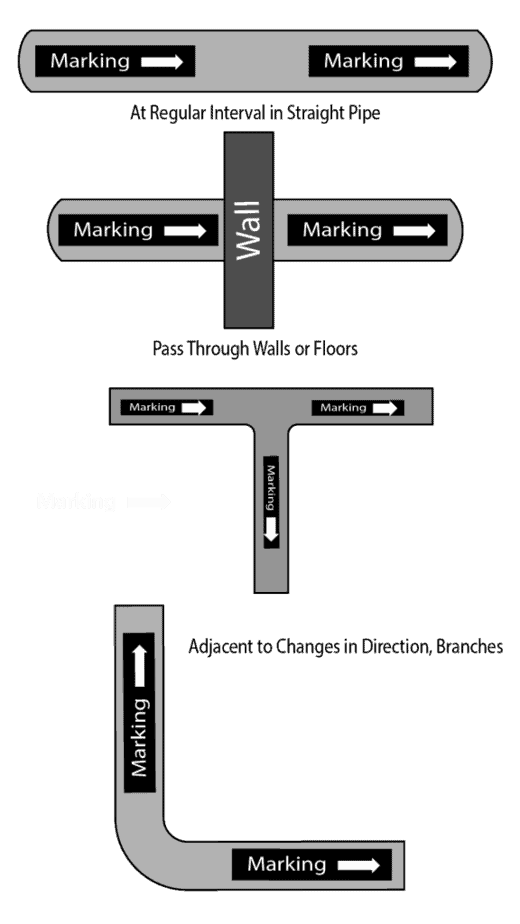
Coloring and identification labels on the pipe should apply in such a way that is clearly visible from all the approaches, especially when pipes are overhead. ASME B13.1 and IS 2379 provide guidance on the positions of the labeling. Refer to the table below for the general guideline provided in the standards.
| Location of the Colour Band | |
|---|---|
| As Per IS -2379 | AS Per BS 1710 & ASME B13.1 |
| At battery limit points | Close to valves or flanges |
| Intersection points and change of direction points in piping ways | Adjacent to changes in direction, branches |
| Other points such as midway of each piping way, near valves, junction joints of service appliances, walls, on either side of pipe culverts | where pipes pass through walls or floors |
| For long stretch yard piping at 50 m interval | at intervals on straight pipe runs sufficient for identification |
| At start and terminating points | |
Are You Piping Components Master?
Don’t forget to Subscribe.
