Process Flow Diagram (PFD) is also known as Process Flow Chart, Process Flowsheets, and Process flow scheme. In this article, you will learn what this drawing is and what type of information is provided in it with the help of a real plant PFD example.
What is the Process Flow Diagram?
A process Flow Diagram (PFD) is a simple drawing that shows the relationships between major equipment in a process plant using equipment symbols and shows a unit’s primary process flow path. You can visualize the flow of material within the plant with the help of these drawings.
What is the use of a Process Flow Diagram?
A process flow diagram provides a quick overview of the entire operating unit or a system. A technician or engineer can use this document to trace the flow of materials through the unit. The flow diagram is also used for visitor information and new employee training.
It is one of the core documents for drawing the Plot Plant and P&ID.
If you don’t want to read, watch this video which will explain to you all aspects covered in this article.
What information does the Process Flow Diagram provide?
A typical PFD will include:
- All Major equipment: Each piece of equipment shown on PFD has a unique equipment number and a descriptive name. It also indicates the equipment’s main dimensions, capacity, and operating information.
- 2nd is – Process flow stream or interconnected piping. PFD follows the left-right approach for process flow. That means any process stream enters or exits either from the right or left. However, please note that this left-right approach is not mandatory but a good engineering practice.
- All process flow streams shown on PFD will have an identification number. A description of the process conditions and the chemical composition of each stream, such as pressure, temperature, density, mass flow rate, and mass-energy balance, will be included in PFD. These data will be either displayed directly on the PFD or included in the flow summary table. Sometimes, it also shows these process parameters’ minimum, normal and maximum values. Next is
- The process flow direction of all process line
- Control valves and process-critical valves
- Major bypass and recirculation systems
- Connections with other systems
P&ID Quiz – Test yourself, Take This Quiz
Unlock New Skills with Our Best Selling Online Courses
What is not included in a PFD?
- Pipe classes and pipeline numbers
- Process control instruments
- Minor bypass valves
- Isolation and shutoff valves
- Maintenance vents and drains
- Relief valves and safety valves and
- Code class information
You must be thinking, if this information is not here, then where are you? Well! This information is covered in P&ID, which is a more complex drawing than PFD.
To read PFD, PFS, P&ID, PEFS, iso, and GA drawings, knowing the various symbols for equipment, valve, and instruments is a must. So if you have not watched the earlier video on P&ID/PFD symbols, please watch that video first.
I will explain to you how to read this PFD or PFS with the help of the real drawing. Check the PFD that you are going to learn.
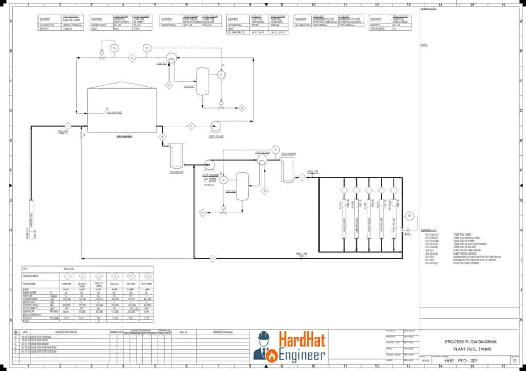
Now, look at this PFS or PFD; well, both are the same. You can see the PFS of the OSBL part of the plant fuel oil and slop tank.
Equipment list on Process Flow Diagram
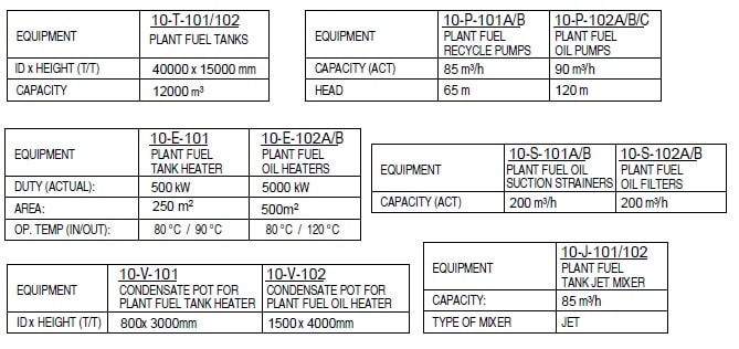
Let’s check the equipment that is used in this system. Here you can see the tank, pumps, exchanger, vessel, strainer, and jet mixture. On top of any PFD, you can see the list of all the major equipment along with its size and capacity.
Lines in PFD
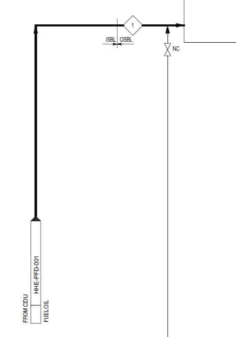
All the main process lines are shown as a dark black lines, and the thin black lines are minor process lines. Aero heads on the line show the direction of the flow.
Fuel oil is coming from other ISBL units. You can see the incoming aero with a dark head. If there is no dark head and simple aero is there like this, it means the line is coming from the same unit.
You can see the battery limit between OSBL and ISBL. This process stream is numbered as one, for which details are given in the table below. A square box with a number inside will give you the process stream number.
A square box with letters inside means it refers to other services, and for the detail of that stream, you refer to the PFD of that process. Here SL means a steam line, and the CL means condensate line.
This is a generic symbol of the valve. If you want to know the exact type of valve, you have to check the P&ID. The letter NC means Normally close. That means this valve remains closed during normal operation.
Tank Section
Now, look at this loop; this is a circulation loop. Fuel oil from the tank is supplied to a pump which will pass through the heat exchanger and return to the tank. You have to maintain the temperature of the fuel otherwise, it will get thick and chock the line and also settle in the tank.
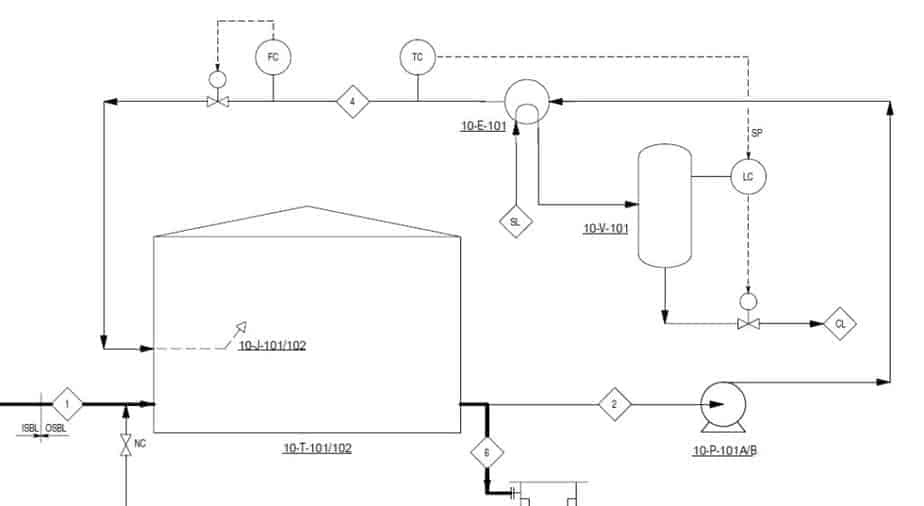
You can see that there are two control valves shown in this loop. One will maintain the temperature by controlling steam, and the second one will maintain the flow. The symbol of the valve is a generic symbol of the remotely actuated valve. It can be the hydraulic, pneumatic, or motor-operated type.
If you are interested in learning more about valves and their function, you can buy my full course on the valve, in which I have covered more than 18 types of valves. Yes, this is marketing because that is how I earn money to produce good-quality videos and articles. So please support me by purchasing my courses.
Now back to our PFD.
Unlock New Skills with Our Best Selling Online Courses
Pump Section of PFD
See this detail of the pump, the recycle pump has a head of 60 meters and the plant fuel oil pump has a head of 216 meters. These must be large pumps. Let’s look where they are in PFD.
Let me adjust the PFD on the screen so that we can conclude our video.
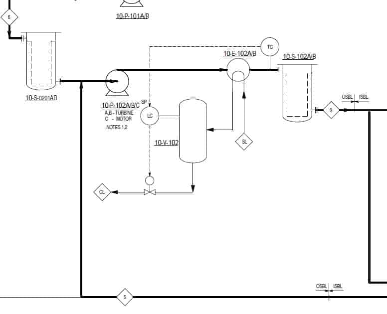
Ooh!! These pumps are turbine driven, which means they are critical pumps. Normally turbine-driven pumps are provided where you want to run the pump even if there is a total power failure in your plant.
Here we have two basket strainers, one on the suction side and another on the pump discharge side, and we also have a heat exchanger to maintain the temperature of fuel oil.
The suction strainer will protect the pump impeller from any foreign object that can damage the pump, and the discharge strainer will ensure a clean supply to user units.
You can see the temperature control loop also.
Here, you can see the battery limits of ISBL and OSBL. Fuel oil is supplied to various ISBL units’ furnaces. On the ISBL side, you can see that one pressure control valve is given, which ensures constant pressure in the Fuel Oil loop.
Now let’s look at the stream table. This table gives many process parameters such as pressure, temperature, flow rate, and other details. Have a look at it.
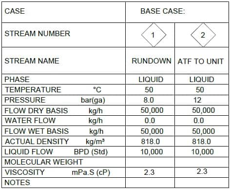
This is all about PFD. You have learned all most all detail that PFD provides. If you want to learn how to read P&ID, you can check the P&ID article here.
Are You Piping Components Master?
