In this article, I will explain you three key failure modes of control valves—Fail-Open, Fail-Closed, and Fail-Lock. As you know Control valves play a critical role in ensuring the safe and efficient operation of process plants. By the end of this article, you’ll have a clear understanding of these failure modes, how they work, and where they are used.
Table of Contents
What is Failure Mode in Control Valves?
Control valves consist of two main components: the valve itself and the actuator. These components work together to regulate pressure, flow, and temperature in process systems. Control valves typically rely on external energy sources such as air, electricity, or hydraulic fluid to operate.
But what happens when these energy sources are lost? This situation is known as the valve’s failure mode—the position the valve assumes when there is a loss of signal or power. The main purpose of failure modes is to maintain safety and prevent equipment damage when something goes wrong.
Fail-Open (FO) Mode
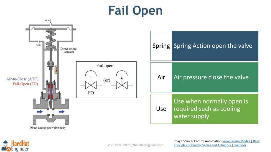
In the Fail-Open mode, the valve moves to the fully open position when it loses power or the control signal.

How Does It Work?
In a Fail-Open setup as shown in the image above, the actuator is direct-acting with a direct-acting valve. The spring force in the actuator keeps the valve open when no external energy is applied. Once air (or another power source) is supplied, the spring is compressed, and the valve closes.
When power or signal is lost, the spring returns to its original position, and the valve reopens.
When to Use Fail-Open Valves?
Fail-Open valves are typically used in systems where it is essential to maintain fluid flow during power failures. For example, they are commonly found in cooling systems to ensure continuous cooling in case of a failure.
Symbol Representation
On a Piping and Instrumentation Diagram (P&ID), the symbol for a Fail-Open valve is often marked with FO underneath the valve symbol, indicating its failure mode. As shown in the image above.
Fail-Closed (FC) Mode
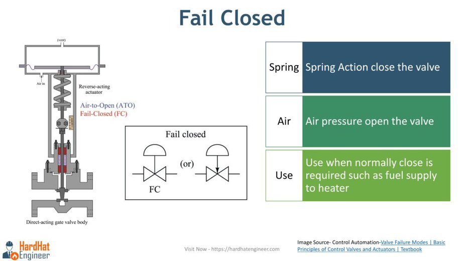
In the Fail-Closed mode, the valve moves to the fully closed position when power or signal is lost.

How Does It Work?
In the above configuration as shown in the image, a reverse-acting actuator is paired with a direct-acting valve. Here, the spring force keeps the valve closed. When air or another power source is applied, the spring compresses, and the valve opens.
When power is lost, the spring forces the valve to close again.
When to Use Fail-Closed Valves?
Fail-Closed valves are ideal for systems where stopping fluid flow is critical during a failure. For instance, they are used in fuel supply systems for heaters or in systems controlling hazardous liquids, where stopping the flow in case of failure is vital for safety.
Symbol Representation
The P&ID symbol for a Fail-Closed valve includes FC beneath the valve symbol to denote its failure mode as shown in the image above.
Fail-Lock (FL) Mode
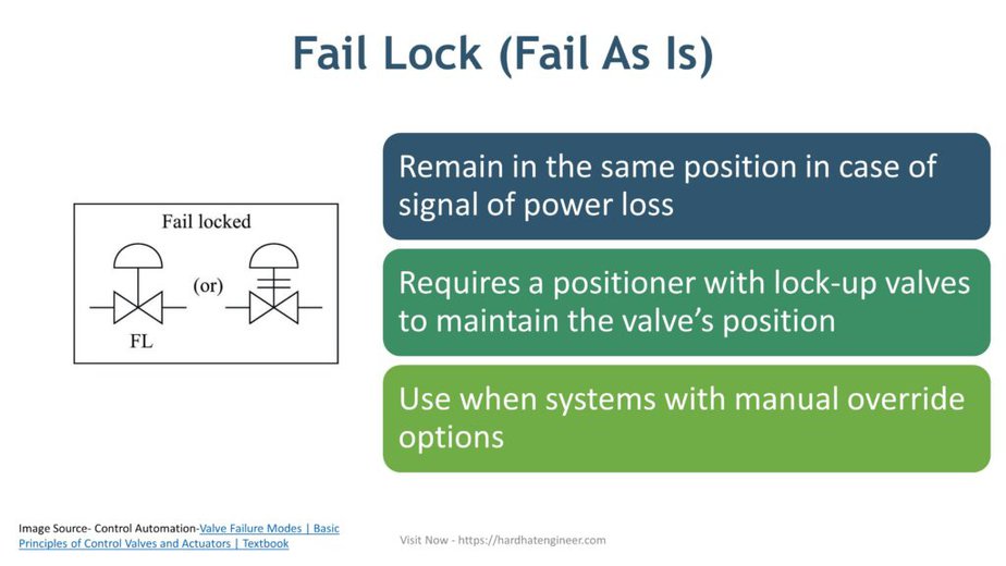
In the Fail-Lock mode, the valve remains in its last position—whether open, closed, or partially open—when power or signal is lost.

How Does It Work?
Unlike Fail-Open or Fail-Closed valves, Fail-Lock valves require additional components, such as a positioner with lock-up valves, to maintain the valve’s position. When external energy is lost, these components hold the valve in its last known position until manual intervention occurs.
When to Use Fail-Lock Valves?
Fail-Lock valves are useful in systems where neither fully opening nor fully closing the valve is ideal during a failure. They are often employed in situations where manual intervention is necessary to restore safe operation.
Symbol Representation
Fail-Lock valves are typically marked with FL beneath the valve symbol on a P&ID, indicating their failure mode.
How Control Valve Failure Mode is Shown in P&ID?

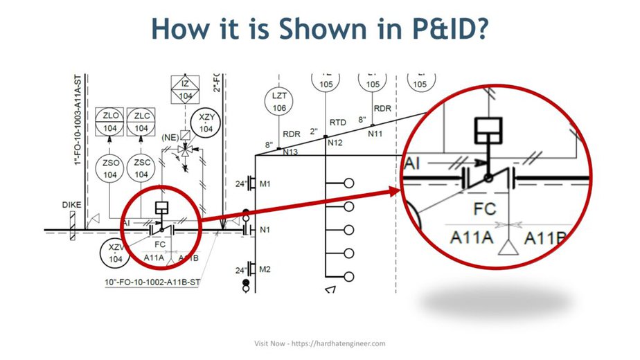
In this part of P&ID, you can see a butterfly-type control valve with a Fail-Close setting. It is connected to a tank, so when there is a loss of signal, the valve will close to prevent the tank from overfilling.
As mentioned earlier, letters like FC (Fail Close), FO (Fail Open), or FL (Fail Lock) below the valve indicate its failure mode.
Image Source Control Automation – Valve Failure Modes | Basic Principles of Control Valves and Actuators | Textbook

