In this article, you are going to learn about different types of valve symbols used in P&ID. Many types of valves are used in process piping, and each has a different symbol. This makes the valve one of the tricky parts of reading P&ID. But with practice, you can easily remember these symbols and can read P&ID effectively.
There are two types of valve symbols — first, generic symbols, and second, a symbol with a modifier. Generic symbols will tell you that there is a valve in the line, but they will not tell you about the types of the valve. Whereas the valve symbol with modifier will tell you the type of valve used in the pipeline.
Generic symbols of Valves
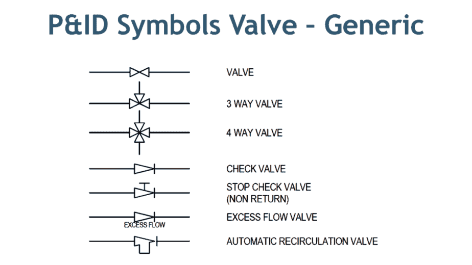
Here in the image above, you can see commonly used symbols for valves. These symbols are generic in nature — for example, the first symbol of a valve.
Now when you look at the symbol on the drawing, it just gives you an indication that some kind of valve is used, but it will not provide you with information about the type of valve, whether it is a gate, globe, or plug type valve. There are dedicated symbols for a gate, globe, plug, and ball valves which I will explain to you in minutes.
Similarly, the next two symbols are for three-way and four-way valves. It can be a plug or ball valve. The subsequent two symbols are a check valve and a stop check valve. These check valves can be swing check or lift check valves.
The next symbol is the excess flow valve. You can see that it is the same as a check valve the only difference is the written text below the valve symbol. You must be very careful while reading this type of symbol as it can easily be overlooked.
The last symbol is of automatic recirculation valve. This type of valve is used in the pump discharge line to ensure the pump will not suffer from low inlet pressure, which leads to cavitation.
Watch this video which will explain to you all aspects covered in this article.
P&ID Quiz – Test yourself, Take This Quiz
Unlock New Skills with Our Best Selling Online Courses
Relief Valve Symbols
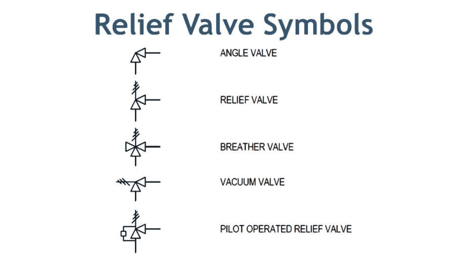
Here in the image above, the first symbol is of angle valve. In most cases, a globe valve is used as an angle valve. The next symbol is the relief valve used to protect the piping system or equipment from overpressure.
Now the breather valve is used on the cone roof tank. This valve serves the function of the relief valve and vacuum valve. In the event of over-pressure, this valve release the pressure, and in case a vacuum is created in the tank, this valve allows air to enter the tank. Just like breathing air in and out.
The vacuum valve prevents damage to the equipment from negative pressure. Pilot-operated relief valves are just working as relief valves but are used for large-size piping. This type uses a small relief valve to operate the main relief valve. This arrangement is cost-effective in large-size relief operations.
Now I will explain to you the specific valve symbol that is used in P&ID and isometric drawings.
If you want to learn about more than 18 types of valves in detail, you can buy my course, how to be an expert in piping valves.
Gate Valve Symbol
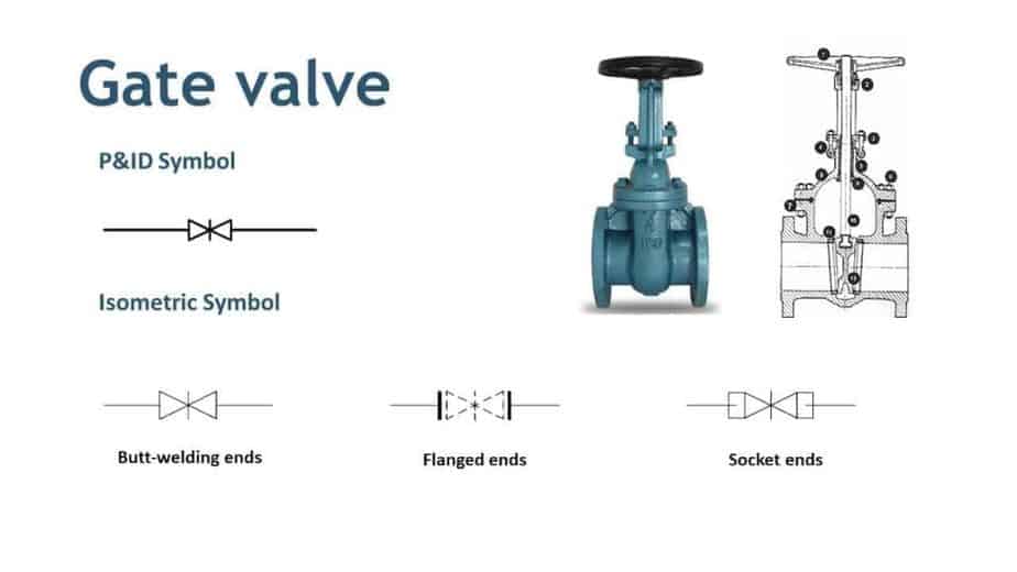
In the image above, you can see the gate valve. Now see the P&ID symbol for the gate valve. It is a modification of a generic valve symbol by inserting a vertical line between two triangles. Three symbols shown below are the gate valve symbols used in isometric drawings. The first is for butt-welding ends, the second is for flanged end valve, and the third is for socket end connection.
Globe Valve Symbol
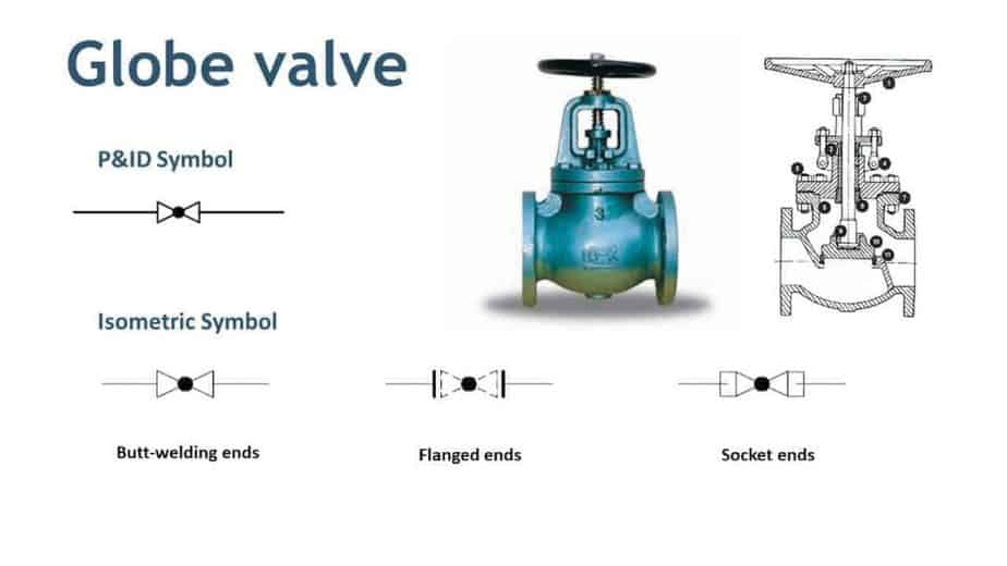
For a globe valve, a symbol is modified by adding a small dark circle between triangles. You can see that P&ID and isometric symbols are almost the same, with the only change in end types.
Ball Valve Symbol
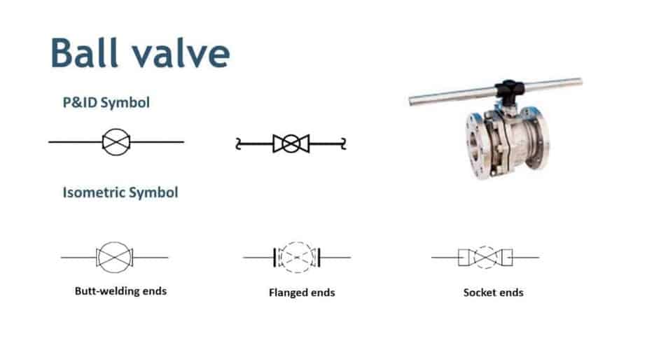
You can see that there are two P&ID symbols for a ball valve. The reason is that P&ID and isometric drawing symbols are changed from company to company. So if you switch the company, you should be aware of this. Similarly, you can see the ISO symbols for butt, flanged, and socket ends ball valve.
Needle Valve Symbol
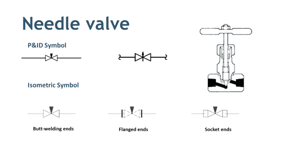
Same as a ball valve, a needle valve also has multiple P&ID symbols. If you can see that even though these symbols are different, you can still easily interpret them. If you are using second P&ID symbols, your isometric symbol will be changed accordingly.
Unlock New Skills with Our Best Selling Online Courses
Plug Valve Symbol
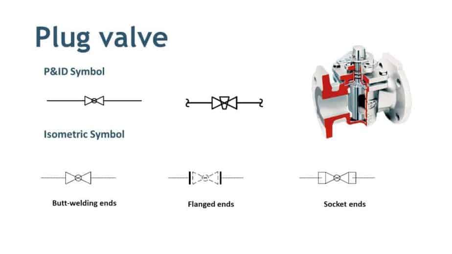
For the plug valve, the first symbol is a bit confusing with a globe valve. If you remember the symbol of a globe valve, it has a dark circle in between the triangle, whereas here, only the circle outline is there. So when you see this type of symbol, better to double-check the drawing.
Butterfly Valve Symbol
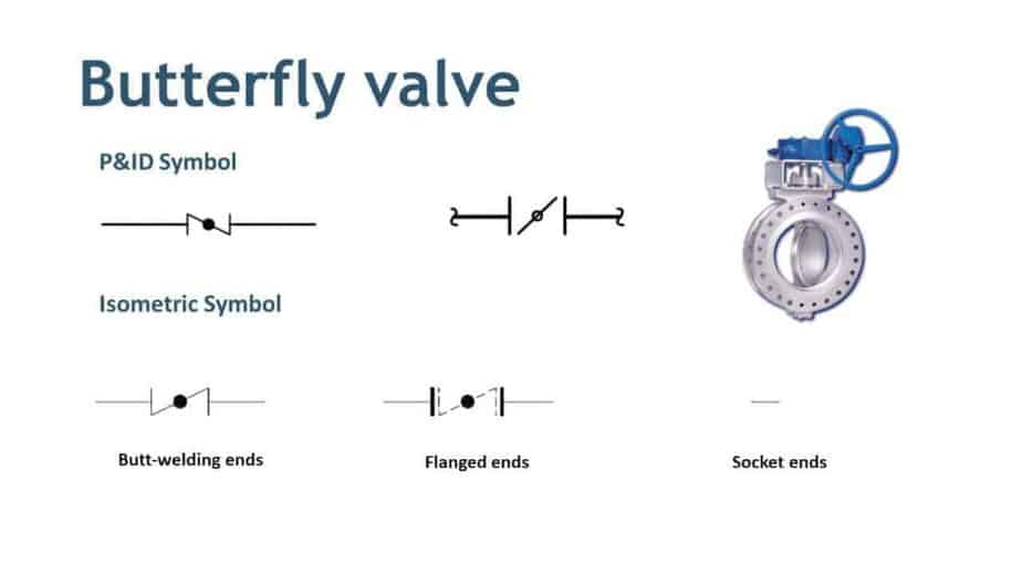
The butterfly valve symbol is the only symbol where a full triangle is not used. If you refer to the first symbol, it is similar to a globe valve, but a triangle is not full. The alternative symbol is clearer in this case. For isometric symbols, you can see that there is no socket end butterfly valve.
Diaphragm Valve Symbol
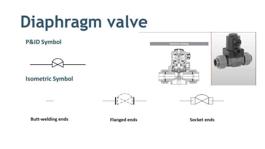
Here is the diaphragm valve. There is no butt-welded diaphragm valve available. Most diaphragm valves are flange type, and they are used to handle process media with solid particles.
Special Valve Symbol
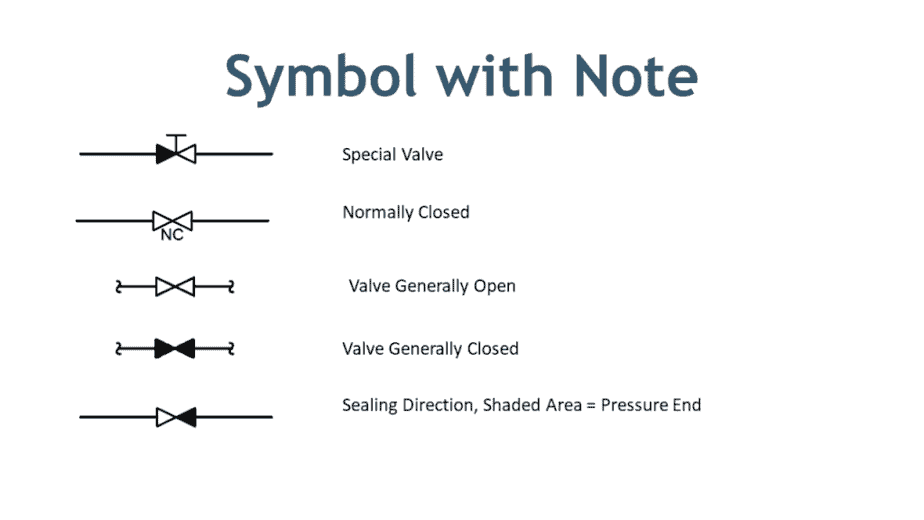
You can see the symbols in the image above with a special note. The first symbol is a special valve. The word NC return below the second symbol is more important. It indicates that this valve remains closed during normal operation. Now the next two symbols are also used alternatively to show the valve position during normal operation.
The last symbol is used to show the pressure end of the valve. The shaded shows the pressure side of the valve.
This is all about P&ID and isometric symbols of Valves. If you want to learn about equipment symbols that use in drawing, check this article.
Are You Piping Components Master?
