A valve is an assembled product. Valve external parts and Valve trim parts such as Body, Bonnet, Disk/wedge, Seat, Stam, Gland Packing / Stud & Bolt / Gasket / Handwheel are all manufactured independently and assembled in a valve factory.
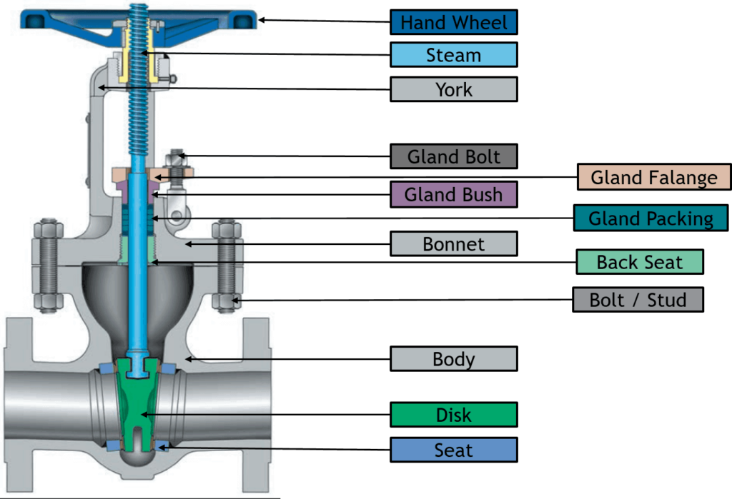
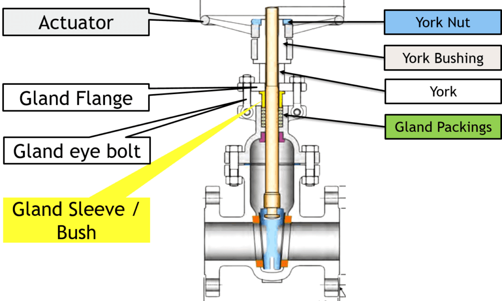
In the image below, you can see the main parts of a valve.
Image – Velan
Unlock New Skills with Our Best Selling Online Courses
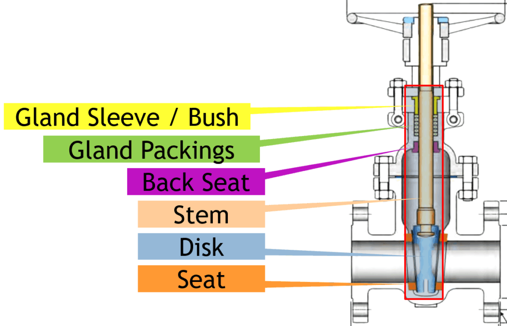
You can see the cutout of the gate valve. The main components of the valve are listed below.
- Body
- Bonnet
- Stem
- Disk/Wedge
- Seat, Packings
- York
- Bolt
- Sleeves
- Actuator
- Backseat
Let’s learn about each of these parts of a valve.
Valve Quiz – Test yourself, Take This Quiz
Valve Body or Shell
The body is the main pressure retaining part and accommodates valve trim. It provides the passage for fluid flow. The body may be cast, forged, or fabricated. Sometimes valve bodies are manufactured by a combination of cast, forged, or fabricated parts. Various metals, alloys, and non-metals are used to manufacture the valve body. The valve body is also known as a shell.
The ends of the valve are designed to connect the valve with pipe or equipment. Ends connections can be a butt, socket, threaded, or flanged type, and sometimes it simply sandwiches between two pipe flanges that are known as wafer ends.
A valve body has different types of passages through which fluid passes. The design of these passages depends on the function of a valve.
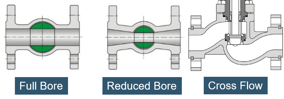
- The first body type is Reduced bore; in this type, the passage diameter of the valve is smaller than the connecting This is the most common design as it will reduce overall valve cost and, at the same time it, narrows the fluid flow.
- The second type is a Full bore; in this type, the inside passage diameter of the valve is the same as connecting pipe. This type of body is used when pigging is required. Pigging is used for various purposes, such as cleaning and inspection of the pipeline.
- The third type is Crossflow or Split section body, this kind of body is used mainly in the globe valve, piston, or plug type check valve.
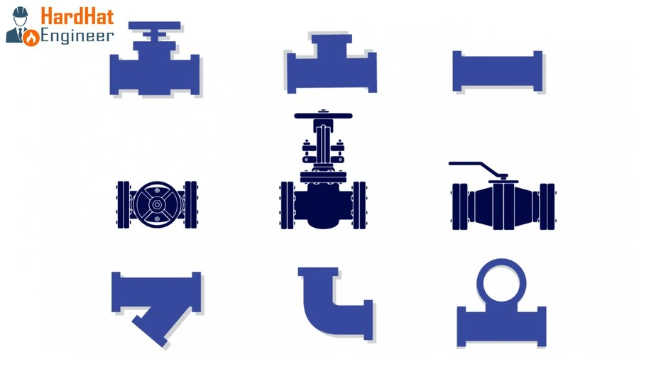
You can see the images of all three types of bodies.
You can now easily work out the difference between the full-bore valve and reducing the bore valve from the above image.
Bonnet or Cover
The cover for the valve body is known as a bonnet. Like valve bodies, bonnets are also available in many designs.
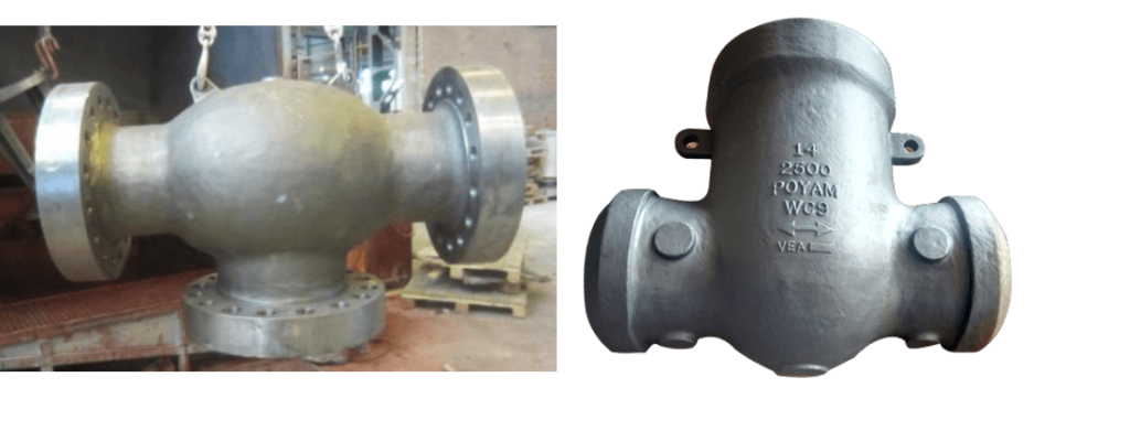
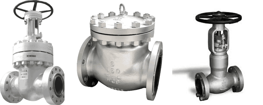
Some bonnets function simply as a valve cover. For example, the swing check valve is shown in the photo. While others support valve internals and accessories such as the stem, disk, and actuator. In the case of the gate, globe, stop check, and diaphragm valves, the bonnet contains an opening for the valve stem to pass through. Usually, a stuffing box is also a part of the bonnet.
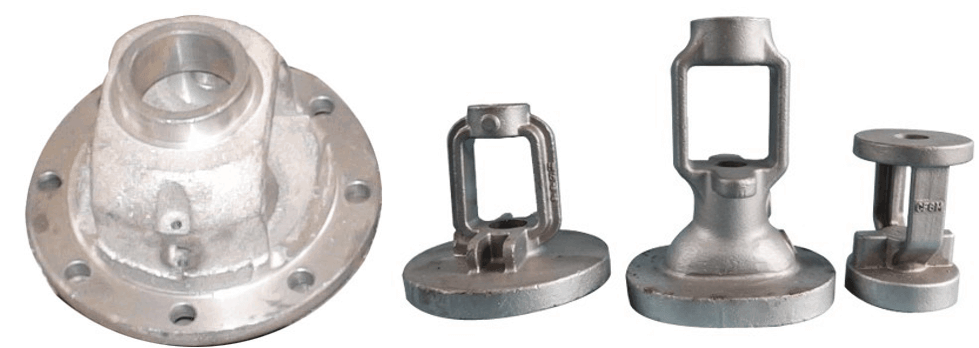
Some valves have a bonnetless design in which the valve body and bonnet are combined into one. You can see the bonnetless valve photo. In a split body ball valve, there is no bonnet because the body is split into two sections.
There are many ways to connect a bonnet with a body, such as bolting, threading, and welding. The body-bonnet joint is one of the primary sources of the leak; that is why it should be a pressure-tight. The bonnet is cast or forged of the same material as the body.
Unlock New Skills with Our Best Selling Online Courses
What is Valve Trim?
The removable and replaceable internal parts of the valve that come in contact with the flow medium are collectively known as valve trim. Disc, valve seat, and stem are common for all the valves.
Valve Trim components will change with the types of valves. Valve-specific trim includes a back seat, glands, spacers, guides, bushings, retaining pins, and internal springs. Here in the image, you can see the gate valve trim parts. Because of the trim parts, disk movement and flow control are possible.
Disk
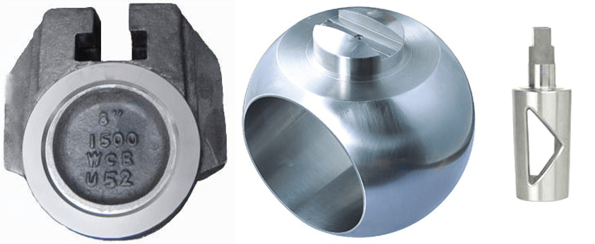
The first valve trim part is a disc. The disc is the part that allows, throttles, or stops fluid flow depending on its position. Types of disks define the name of the valve such as gate, ball, plug, and needle valve’s disk are also of the same shape as the name.
A valve disc could be cast, forged, or fabricated. The valve disk is sometimes required hard facing to improve wear resistance. Disk needed smooth machine surface to reduce the friction with a seat. The valve disk is a pressure-retaining part.
That means the disk holds the pressure. When the valve is open, the disc does not perform pressure-retaining or -containing functions. However, when the valve is closed, the disc performs pressure-retaining functions.
A disc rests against the stationary valve seat when the valve is in the closed position. It can be moved away from the seat by the movement of the stem. However, in check and safety-relief valves, fluid flow and pressure move the disc away from the seat.
Seat
The seat provides the seating surface for the disk. Here, you can see the gate valve seat in the above image. A valve may have multiple seats. In the case of a globe valve and swing-check valve, there is one seat. A gate valve and ball valve have two seats; one on the upstream side and the other on the downstream side.
The valve leakage rate is directly proportional to the effectiveness of the seal between the valve disc and seat(s). Valve seats may be integral or replaceable rings. Valves are generally provided with a screwed, welded, or integrally cast or forged seat and hardened by heat treatment or by the hard facing of Stellite weld overlay.
A fine surface finish of the seating area is necessary for proper sealing. Some ball valves & plug valves used the non-metallic seat for non-critical services. Valve manufacturers have developed several designs of combination valve seats involving elastomer and metal seats that are effective in achieving the desired leak tightness, which cannot be achieved only by metal seats.
Back Seat
The back seat is comprised of a shoulder on the stem and a mating surface on the underside of the bonnet. You can see it in the image. It forms a seal when the stem is in a fully open position. It prevents leakage of flow medium to the packing chamber and consequently to the environment. The back seat enables the replacement of the gland packing when the valve is in service.
Stem
The stem connects the actuator and disk. It moves and positions the valve disk. The valve stem transports the required motion to the disc, plug, or ball for opening, closing, or positioning the valve. The stem connects the actuator, handwheel, or the lever of the valve at one end and the disc on the other end.
In gate and globe valves, the linear motion of the disc opens or closes the valve, while in the plug, ball, and butterfly valves, the disc rotates to open or shut the valve. Stems are typically forged from stainless steel and connected to the disk by threaded or welded joints.
Bonnet Bolt & Gland Eyebolt
Bonnet bolt or stud, hold the bonnet and body to create a presser tight seal between them. Gland eyebolt serves two functions. First, it connects the gland flange and bonnet. Second, when you tighten the bolt, it pushes the gland bush to retain gland packing in the stuffing box.
York, Yoke Bushing, Yoke Nut
The yoke is also called arms. It connects the valve body or bonnet with the actuating mechanism. The yoke and bonnet are designed as a one-piece construction in many valve designs. A yoke must be sturdy enough to withstand forces, moments, and torque developed by the actuator.
The top of the yoke holds a yoke nut. The valve stem passes through the York. It converts the rotary motion of the actuator into linear motion and moves the valve stem.
Yoke Bushings, also known as stem nut, is an internally threaded nut held at the top of a yoke through which the valve stem pass. Usually, the yoke nut and bush are made of a softer material than the stem to reduce the effort of valve opening. Valves that require greater effort to open or close are provided with anti-freeze yoke-sleeve bearings that minimize the friction between the hardened stem and the yoke bushing.
Non-pressure Retaining Parts of a Valve
Gland Flange is used to provide support to the gland bush to keep the gland packing under tension in the stuffing box.
The Bush or Gland sleeve keeps the gland packing inside the stuffing box.
Stem packing or Gland packing or contained in the stuffing box. Gland packings are made from graphite or PTFE as required by services. Proper compression of gland packing is required to prevent the leak from the stem.
With the help of gland flange and sleeve, you can compress the gland packing. Gland packing is one of the primary sources of fugitive emission in a process plant. Regular maintenance is required to ensure the proper function of packing.
Valve Trim Chart
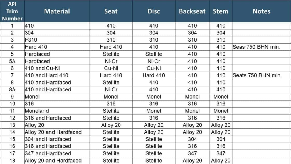
Trim materials such as disks, seats, stem, back sheet, and sleeves are grouped together and assigned one number called Trim No. or Combination number. This will element the requirement of defining material grade for each component.
- API 600 & 602 gives the list of Trim material that can be used in the valve.
- The most common trim grades are ASTM A410(13Cr), ASTM A316, Alloy 20 (19Cr-29Ni), and Monel (CuNi Alloy).
Here in the image, you can see the simplified chart of the trim material. Against trim number, the seat, disc, backseat, and stem material are specified. This makes it easier to order the valve as you just have to specify trim no based on the requirements and need not specify the material for each of the parts. This list is included in the resource section.
Unlock New Skills with Our Best Selling Online Courses
