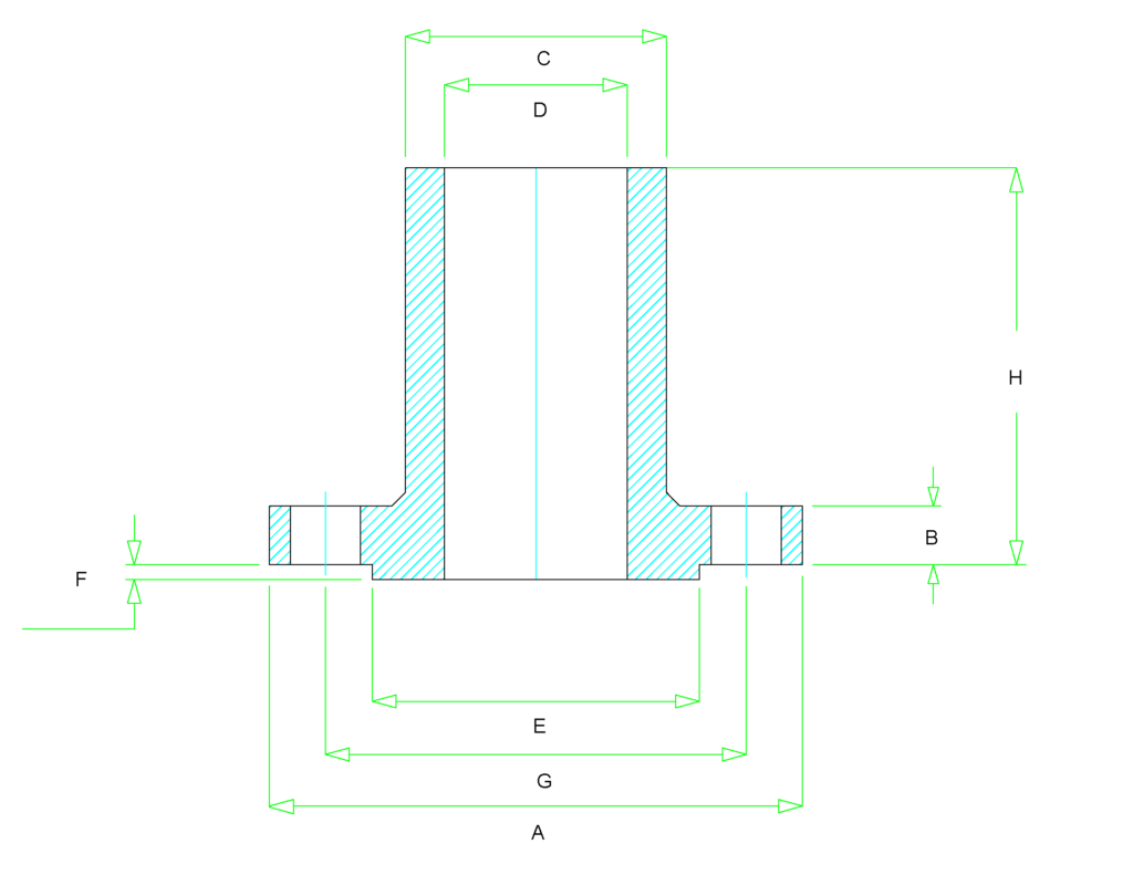
Long Weld neck flange dimensions are covered in ASME B16.5 – which covers Pipe Flanges and Flanged Fittings for size NPS ½” to 24” for above NPS 26” to 60” it should be as per ASME B16.47.
During the dimensional inspection of a flange, you should check for
- Outer & Inner Diameter of body
- Bolt Circle & Bolt hole Diameter
- The thickness of the weld end
- Length of the Hub
- Straightness and alignment of the bolt hole
Class 150 Long Weld Neck Flange Dimensions
| Size in Inch | Size in mm | Outer Dia. | Flange Thick. | Hub OD | Weld Neck OD | RF Dia. | RF Height | PCD | Hub Length | No of Bolts | Bolt Size UNC | Machine Bolt Length | RF Stud Length | Hole Size | ISO Stud Size |
|---|---|---|---|---|---|---|---|---|---|---|---|---|---|---|---|
| A | B | C | D | E | F | G | H | ||||||||
| 1/2 | 15 | 90 | 9.6 | 30 | 21.3 | 34.9 | 2 | 60.3 | As Required | 4 | 1/2 | 50 | 55 | 5/8 | M14 |
| 3/4 | 20 | 100 | 11.2 | 38 | 26.7 | 42.9 | 2 | 69.9 | As Required | 4 | 1/2 | 50 | 65 | 5/8 | M14 |
| 1 | 25 | 110 | 12.7 | 49 | 33.4 | 50.8 | 2 | 79.4 | As Required | 4 | 1/2 | 55 | 65 | 5/8 | M14 |
| 1 1/4 | 32 | 115 | 14.3 | 59 | 42.2 | 63.5 | 2 | 88.9 | As Required | 4 | 1/2 | 55 | 70 | 5/8 | M14 |
| 1 1/2 | 40 | 125 | 15.9 | 65 | 48.3 | 73 | 2 | 98.4 | As Required | 4 | 1/2 | 65 | 70 | 5/8 | M14 |
| 2 | 50 | 150 | 17.5 | 78 | 60.3 | 92.1 | 2 | 120.7 | As Required | 4 | 5/8 | 70 | 85 | 3/4 | M16 |
| 2 1/2 | 65 | 180 | 20.7 | 90 | 73 | 104.8 | 2 | 139.7 | As Required | 4 | 5/8 | 75 | 90 | 3/4 | M16 |
| 3 | 80 | 190 | 22.3 | 108 | 88.9 | 127 | 2 | 152.4 | As Required | 4 | 5/8 | 75 | 90 | 3/4 | M16 |
| 3 1/2 | 90 | 215 | 22.3 | 122 | 101.6 | 139.7 | 2 | 177.8 | As Required | 8 | 5/8 | 75 | 90 | 3/4 | M16 |
| 4 | 100 | 230 | 22.3 | 135 | 114.3 | 157.2 | 2 | 190.5 | As Required | 8 | 5/8 | 75 | 90 | 3/4 | M16 |
| 5 | 125 | 255 | 22.3 | 164 | 141.3 | 185.7 | 2 | 215.9 | As Required | 8 | 3/4 | 85 | 95 | 7/8 | M20 |
| 6 | 150 | 280 | 23.9 | 192 | 168.3 | 215.9 | 2 | 241.3 | As Required | 8 | 3/4 | 85 | 100 | 7/8 | M20 |
| 8 | 200 | 345 | 27 | 246 | 219.1 | 269.9 | 2 | 298.5 | As Required | 8 | 3/4 | 90 | 110 | 7/8 | M20 |
| 10 | 250 | 405 | 28.6 | 305 | 273 | 323.8 | 2 | 362 | As Required | 12 | 7/8 | 100 | 115 | 1 | M24 |
| 12 | 300 | 485 | 30.2 | 365 | 323.8 | 381 | 2 | 431.8 | As Required | 12 | 7/8 | 100 | 120 | 1 | M24 |
| 14 | 350 | 535 | 33.4 | 400 | 355.6 | 412.8 | 2 | 476.3 | As Required | 12 | 1 | 115 | 135 | 1 1/8 | M27 |
| 16 | 400 | 595 | 35 | 457 | 406.4 | 469.9 | 2 | 539.8 | As Required | 16 | 1 | 115 | 135 | 1 1/8 | M27 |
| 18 | 450 | 635 | 38.1 | 505 | 457.2 | 533.4 | 2 | 577.9 | As Required | 16 | 1 1/8 | 125 | 145 | 1 1/4 | M30 |
| 20 | 500 | 700 | 41.3 | 559 | 508 | 584.2 | 2 | 635 | As Required | 20 | 1 1/8 | 140 | 160 | 1 1/4 | M30 |
| 24 | 600 | 815 | 46.1 | 663 | 610 | 692.2 | 2 | 749.3 | As Required | 20 | 1 1/4 | 150 | 170 | 1 3/8 | M33 |
Unlock New Skills with Our Best Selling Online Courses
Class 300 Long Weld Neck Flange Dimensions
| Size in Inch | Size in mm | Outer Dia. | Flange Thick. | Hub OD | Weld Neck OD | RF Dia. | RF Height | PCD | Hub Length | No of Bolts | Bolt Size UNC | Machine Bolt Length | RF Stud Length | Hole Size | ISO Stud Size |
|---|---|---|---|---|---|---|---|---|---|---|---|---|---|---|---|
| A | B | C | D | E | F | G | H | ||||||||
| 1/2 | 15 | 95 | 12.7 | 38 | 21.3 | 34.9 | 2 | 66.7 | As Required | 4 | 1/2 | 55 | 65 | 5/8 | M14 |
| 3/4 | 20 | 115 | 14.3 | 48 | 26.7 | 42.9 | 2 | 82.6 | As Required | 4 | 5/8 | 65 | 75 | 3/4 | M16 |
| 1 | 25 | 125 | 15.9 | 54 | 33.4 | 50.8 | 2 | 88.9 | As Required | 4 | 5/8 | 65 | 75 | 3/4 | M16 |
| 1 1/4 | 32 | 135 | 17.5 | 64 | 42.2 | 63.5 | 2 | 98.4 | As Required | 4 | 5/8 | 70 | 85 | 3/4 | M16 |
| 1 1/2 | 40 | 155 | 19.1 | 70 | 48.3 | 73 | 2 | 114.3 | As Required | 4 | 3/4 | 75 | 90 | 7/8 | M20 |
| 2 | 50 | 165 | 20.7 | 84 | 60.3 | 92.1 | 2 | 127 | As Required | 8 | 5/8 | 75 | 90 | 3/4 | M16 |
| 2 1/2 | 65 | 190 | 23.9 | 100 | 73 | 104.8 | 2 | 149.2 | As Required | 8 | 3/4 | 85 | 100 | 7/8 | M20 |
| 3 | 80 | 210 | 27 | 117 | 88.9 | 127 | 2 | 168.3 | As Required | 8 | 3/4 | 90 | 110 | 7/8 | M20 |
| 3 1/2 | 90 | 230 | 28.6 | 133 | 101.6 | 139.7 | 2 | 184.2 | As Required | 8 | 3/4 | 95 | 110 | 7/8 | M20 |
| 4 | 100 | 255 | 30.2 | 146 | 114.3 | 157.2 | 2 | 200 | As Required | 8 | 3/4 | 95 | 115 | 7/8 | M20 |
| 5 | 125 | 280 | 33.4 | 178 | 141.3 | 185.7 | 2 | 235 | As Required | 8 | 3/4 | 110 | 120 | 7/8 | M20 |
| 6 | 150 | 320 | 35 | 206 | 168.3 | 215.9 | 2 | 269.9 | As Required | 12 | 3/4 | 110 | 120 | 7/8 | M20 |
| 8 | 200 | 380 | 39.7 | 260 | 219.1 | 269.9 | 2 | 330.2 | As Required | 12 | 7/8 | 120 | 140 | 1 | M24 |
| 10 | 250 | 445 | 46.1 | 321 | 273 | 323.8 | 2 | 387.4 | As Required | 16 | 1 | 140 | 160 | 1 1/8 | M27 |
| 12 | 300 | 520 | 49.3 | 375 | 323.8 | 381 | 2 | 450.8 | As Required | 16 | 1 1/8 | 145 | 170 | 1 1/4 | M30 |
| 14 | 350 | 585 | 52.4 | 425 | 355.6 | 412.8 | 2 | 514.4 | As Required | 20 | 1 1/8 | 160 | 180 | 1 1/4 | M30 |
| 16 | 400 | 650 | 55.6 | 483 | 406.4 | 469.9 | 2 | 571.5 | As Required | 20 | 1 1/4 | 165 | 190 | 1 3/8 | M33 |
| 18 | 450 | 710 | 58.8 | 533 | 457 | 533.4 | 2 | 628.6 | As Required | 24 | 1 1/4 | 170 | 195 | 1 3/8 | M33 |
| 20 | 500 | 775 | 62 | 587 | 508 | 584.2 | 2 | 685.8 | As Required | 24 | 1 1/4 | 185 | 205 | 1 3/8 | M33 |
| 24 | 600 | 915 | 68.3 | 702 | 610 | 692.2 | 2 | 812.8 | As Required | 24 | 1 1/2 | 205 | 230 | 1 5/8 | M39 |
Flange and Olet Quiz – Test yourself, Take This Quiz
Class 400 Long Weld Neck Flange Dimensions
| Size in Inch | Size in mm | Outer Dia. | Flange Thick. | Hub OD | Weld Neck OD | RF Dia. | RF Height | PCD | Hub Length | No of Bolts | Bolt Size UNC | RF Stud Length | Hole Size | ISO Stud Size |
|---|---|---|---|---|---|---|---|---|---|---|---|---|---|---|
| A | B | C | D | E | F | G | H | |||||||
| 1/2 | 15 | 95 | 14.3 | 38 | 21.3 | 34.9 | 7 | 66.7 | As Required | 4 | 1/2 | 75 | 5/8 | M14 |
| 3/4 | 20 | 115 | 15.9 | 48 | 26.7 | 42.9 | 7 | 82.6 | As Required | 4 | 5/8 | 90 | 3/4 | M16 |
| 1 | 25 | 125 | 17.5 | 54 | 33.4 | 50.8 | 7 | 88.9 | As Required | 4 | 5/8 | 90 | 3/4 | M16 |
| 1 1/4 | 32 | 135 | 20.7 | 64 | 42.2 | 63.5 | 7 | 98.4 | As Required | 4 | 5/8 | 95 | 3/4 | M16 |
| 1 1/2 | 40 | 155 | 22.3 | 70 | 48.3 | 73 | 7 | 114.3 | As Required | 4 | 3/4 | 110 | 7/8 | M20 |
| 2 | 50 | 165 | 25.4 | 84 | 60.3 | 92.1 | 7 | 127 | As Required | 8 | 5/8 | 110 | 3/4 | M16 |
| 2 1/2 | 65 | 190 | 28.6 | 100 | 73 | 104.8 | 7 | 149.2 | As Required | 8 | 3/4 | 120 | 7/8 | M20 |
| 3 | 80 | 210 | 31.8 | 117 | 88.9 | 127 | 7 | 168.3 | As Required | 8 | 3/4 | 125 | 7/8 | M20 |
| 3 1/2 | 90 | 230 | 35 | 133 | 101.6 | N/A | 7 | 184.2 | As Required | 8 | 7/8 | 140 | 1 | M24 |
| 4 | 100 | 255 | 35 | 146 | 114.3 | 157.2 | 7 | 200 | As Required | 8 | 7/8 | 140 | 1 | M24 |
| 5 | 125 | 280 | 38.1 | 178 | 141.3 | 185.7 | 7 | 235 | As Required | 8 | 7/8 | 145 | 1 | M24 |
| 6 | 150 | 320 | 41.3 | 206 | 168.3 | 215.9 | 7 | 269.9 | As Required | 12 | 7/8 | 150 | 1 | M24 |
| 8 | 200 | 380 | 47.7 | 260 | 219.1 | 269.9 | 7 | 330 | As Required | 12 | 1 | 170 | 1 1/8 | M27 |
| 10 | 250 | 445 | 54 | 321 | 273 | 323.8 | 7 | 387.4 | As Required | 16 | 1 1/8 | 190 | 1 1/4 | M30 |
| 12 | 300 | 520 | 57.2 | 375 | 323.8 | 381 | 7 | 450.8 | As Required | 16 | 1 1/4 | 205 | 1 3/8 | M33 |
| 14 | 350 | 585 | 60.4 | 425 | 355.6 | 412.8 | 7 | 514.4 | As Required | 20 | 1 1/4 | 210 | 1 3/8 | M33 |
| 16 | 400 | 650 | 63.5 | 483 | 406.4 | 469.9 | 7 | 571.5 | As Required | 20 | 1 3/8 | 220 | 1 1/2 | M36 |
| 18 | 450 | 710 | 66.7 | 533 | 457 | 533.4 | 7 | 628.6 | As Required | 24 | 1 3/8 | 230 | 1 1/2 | M36 |
| 20 | 500 | 775 | 69.9 | 587 | 508 | 584.2 | 7 | 685.8 | As Required | 24 | 1 1/2 | 240 | 1 3/4 | M39 |
| 24 | 600 | 915 | 76.2 | 702 | 610 | 692.2 | 7 | 812.8 | As Required | 24 | 1 3/4 | 265 | 1 7/8 | M45 |
Unlock New Skills with Our Best Selling Online Courses
Class 600 Long Weld Neck Flange Dimensions
| Size in Inch | Size in mm | Outer Dia. | Flange Thick. | Hub OD | Weld Neck OD | RF Dia. | RF Height | PCD | Hub Length | No of Bolts | Bolt Size UNC | RF Stud Length | Hole Size | ISO Stud Size |
|---|---|---|---|---|---|---|---|---|---|---|---|---|---|---|
| A | B | C | D | E | F | G | H | |||||||
| 1/2 | 15 | 95 | 14.3 | 38 | 21.3 | 34.9 | 7 | 66.7 | As Required | 4 | 1/2 | 75 | 5/8 | M14 |
| 3/4 | 20 | 115 | 15.9 | 48 | 26.7 | 42.9 | 7 | 82.6 | As Required | 4 | 5/8 | 90 | 3/4 | M16 |
| 1 | 25 | 125 | 17.5 | 54 | 33.4 | 50.8 | 7 | 88.9 | As Required | 4 | 5/8 | 90 | 3/4 | M16 |
| 1 1/4 | 32 | 135 | 20.7 | 64 | 42.2 | 63.5 | 7 | 98.4 | As Required | 4 | 5/8 | 95 | 3/4 | M16 |
| 1 1/2 | 40 | 155 | 22.3 | 70 | 48.3 | 73 | 7 | 114.3 | As Required | 4 | 3/4 | 110 | 7/8 | M20 |
| 2 | 50 | 165 | 25.4 | 84 | 60.3 | 92.1 | 7 | 127 | As Required | 8 | 5/8 | 110 | 3/4 | M16 |
| 2 1/2 | 65 | 190 | 28.6 | 100 | 73 | 104.8 | 7 | 149.2 | As Required | 8 | 3/4 | 120 | 7/8 | M20 |
| 3 | 80 | 210 | 31.8 | 117 | 88.9 | 127 | 7 | 168.3 | As Required | 8 | 3/4 | 125 | 7/8 | M20 |
| 3 1/2 | 90 | 230 | 35 | 133 | 101.6 | N/A | 7 | 184.2 | As Required | 8 | 7/8 | 140 | 1 | M24 |
| 4 | 100 | 275 | 38.1 | 152 | 114.3 | 157.2 | 7 | 215.9 | As Required | 8 | 7/8 | 145 | 1 | M24 |
| 5 | 125 | 330 | 44.5 | 189 | 141.3 | 185.7 | 7 | 266.7 | As Required | 8 | 1 | 165 | 1 1/8 | M27 |
| 6 | 150 | 355 | 47.7 | 222 | 168.3 | 215.9 | 7 | 292.1 | As Required | 12 | 1 | 170 | 1 1/8 | M27 |
| 8 | 200 | 420 | 55.6 | 273 | 219.1 | 269.9 | 7 | 349.2 | As Required | 12 | 1 1/8 | 190 | 1 1/4 | M30 |
| 10 | 250 | 510 | 63.5 | 343 | 273 | 323.8 | 7 | 431.8 | As Required | 16 | 1 1/4 | 215 | 1 3/8 | M33 |
| 12 | 300 | 560 | 66.7 | 400 | 323.8 | 381 | 7 | 489 | As Required | 20 | 1 1/4 | 220 | 1 3/8 | M33 |
| 14 | 350 | 605 | 69.9 | 432 | 355.6 | 412.8 | 7 | 527 | As Required | 20 | 1 3/8 | 235 | 1 1/2 | M36 |
| 16 | 400 | 685 | 76.2 | 495 | 406.4 | 469.9 | 7 | 603.2 | As Required | 20 | 1 1/2 | 255 | 1 5/8 | M39 |
| 18 | 450 | 745 | 82.6 | 546 | 457 | 533.4 | 7 | 654 | As Required | 20 | 1 5/8 | 275 | 1 3/4 | M42 |
| 20 | 500 | 815 | 88.9 | 610 | 508 | 584.2 | 7 | 723.9 | As Required | 24 | 1 5/8 | 285 | 1 3/4 | M42 |
Class 900 Long Weld Neck Flange Dimensions
| Size in Inch | Size in mm | Outer Dia. | Flange Thick. | Hub OD | Weld Neck OD | RF Dia. | RF Height | PCD | Hub Length | No of Bolts | Bolt Size UNC | RF Stud Length | Hole Size | ISO Stud Size |
|---|---|---|---|---|---|---|---|---|---|---|---|---|---|---|
| A | B | C | D | E | F | G | H | |||||||
| 1/2 | 15 | 120 | 22.3 | 38 | 21.3 | 34.9 | 7 | 82.6 | As Required | 4 | 3/4 | 110 | 7/8 | M20 |
| 3/4 | 20 | 130 | 25.4 | 44 | 26.7 | 42.9 | 7 | 88.9 | As Required | 4 | 3/4 | 115 | 7/8 | M20 |
| 1 | 25 | 150 | 28.6 | 52 | 33.4 | 50.8 | 7 | 101.6 | As Required | 4 | 7/8 | 125 | 1 | M24 |
| 1 1/4 | 32 | 160 | 28.6 | 64 | 42.2 | 63.5 | 7 | 111.1 | As Required | 4 | 7/8 | 125 | 1 | M24 |
| 1 1/2 | 40 | 180 | 31.8 | 70 | 48.3 | 73 | 7 | 123.8 | As Required | 4 | 1 | 140 | 1 1/8 | M27 |
| 2 | 50 | 215 | 38.1 | 105 | 60.3 | 92.1 | 7 | 165.1 | As Required | 8 | 7/8 | 145 | 1 | M24 |
| 2 1/2 | 65 | 245 | 41.3 | 124 | 73 | 104.8 | 7 | 190.5 | As Required | 8 | 1 | 160 | 1 1/8 | M27 |
| 3 | 80 | 240 | 38.1 | 127 | 88.9 | 127 | 7 | 190.5 | As Required | 8 | 7/8 | 145 | 1 | M24 |
| 4 | 100 | 290 | 44.5 | 159 | 114.3 | 157.2 | 7 | 235 | As Required | 8 | 1 1/8 | 170 | 1 1/4 | M30 |
| 5 | 125 | 350 | 50.8 | 190 | 141.3 | 185.7 | 7 | 279.4 | As Required | 8 | 1 1/4 | 190 | 1 3/8 | M33 |
| 6 | 150 | 380 | 55.6 | 235 | 168.3 | 215.9 | 7 | 317.5 | As Required | 12 | 1 1/8 | 190 | 1 1/4 | M30 |
| 8 | 200 | 470 | 63.5 | 298 | 219.1 | 269.9 | 7 | 393.7 | As Required | 12 | 1 3/8 | 220 | 1 1/2 | M36 |
| 10 | 250 | 545 | 69.9 | 368 | 273 | 323.8 | 7 | 469.9 | As Required | 16 | 1 3/8 | 235 | 1 1/2 | M36 |
| 12 | 300 | 610 | 79.4 | 419 | 323.8 | 381 | 7 | 533.4 | As Required | 20 | 1 3/8 | 255 | 1 1/2 | M36 |
| 14 | 350 | 640 | 85.8 | 451 | 355.6 | 412.8 | 7 | 558.8 | As Required | 20 | 1 1/2 | 275 | 1 5/8 | M39 |
| 16 | 400 | 705 | 88.9 | 508 | 406.4 | 469.9 | 7 | 616 | As Required | 20 | 1 5/8 | 285 | 1 3/4 | M42 |
| 18 | 450 | 785 | 101.6 | 565 | 457 | 533.4 | 7 | 685.8 | As Required | 20 | 1 7/8 | 325 | 2 | M48 |
| 20 | 500 | 855 | 108 | 622 | 508 | 584.2 | 7 | 749.3 | As Required | 20 | 2 | 350 | 2 1/8 | M52 |
| 24 | 600 | 1040 | 139.7 | 749 | 610 | 692.2 | 7 | 901.7 | As Required | 20 | 2 1/2 | 440 | 2 5/8 | M64 |
Unlock New Skills with Our Best Selling Online Courses
Class 1500 Long Weld Neck Flange Dimensions
| Size in Inch | Size in mm | Outer Dia. | Flange Thick. | Hub OD | Weld Neck OD | RF Dia. | RF Height | PCD | Hub Length | No of Bolts | Bolt Size UNC | RF Stud Length | Hole Size | ISO Stud Size |
|---|---|---|---|---|---|---|---|---|---|---|---|---|---|---|
| A | B | C | D | E | F | G | H | |||||||
| 1/2 | 15 | 120 | 22.3 | 38 | 21.3 | 34.9 | 7 | 82.6 | As Required | 4 | 3/4 | 110 | 7/8 | M20 |
| 3/4 | 20 | 130 | 25.4 | 44 | 26.7 | 42.9 | 7 | 88.9 | As Required | 4 | 3/4 | 115 | 7/8 | M20 |
| 1 | 25 | 150 | 28.6 | 52 | 33.4 | 50.8 | 7 | 101.6 | As Required | 4 | 7/8 | 125 | 1 | M24 |
| 1 1/4 | 32 | 160 | 28.6 | 64 | 42.2 | 63.5 | 7 | 111.1 | As Required | 4 | 7/8 | 125 | 1 | M24 |
| 1 1/2 | 40 | 180 | 31.8 | 70 | 48.3 | 73 | 7 | 123.8 | As Required | 4 | 1 | 140 | 1 1/8 | M27 |
| 2 | 50 | 215 | 38.1 | 105 | 60.3 | 92.1 | 7 | 165.1 | As Required | 8 | 7/8 | 145 | 1 | M24 |
| 2 1/2 | 65 | 245 | 41.3 | 124 | 73 | 104.8 | 7 | 190.5 | As Required | 8 | 1 | 160 | 1 1/8 | M27 |
| 3 | 80 | 265 | 47.7 | 133 | 88.9 | 127 | 7 | 203.2 | As Required | 8 | 1 1/8 | 180 | 1 1/4 | M30 |
| 4 | 100 | 310 | 54 | 162 | 114.3 | 157.2 | 7 | 241.3 | As Required | 8 | 1 1/4 | 195 | 1 3/8 | M33 |
| 5 | 125 | 375 | 73.1 | 197 | 141.3 | 185.7 | 7 | 292.1 | As Required | 8 | 1 1/2 | 250 | 1 5/8 | M39 |
| 6 | 150 | 395 | 82.6 | 229 | 168.3 | 215.9 | 7 | 317.5 | As Required | 12 | 1 3/8 | 260 | 1 1/2 | M36 |
| 8 | 200 | 485 | 92.1 | 292 | 219.1 | 269.9 | 7 | 393.7 | As Required | 12 | 1 5/8 | 290 | 1 3/4 | M42 |
| 10 | 250 | 585 | 108 | 368 | 273 | 323.8 | 7 | 482.6 | As Required | 12 | 1 7/8 | 335 | 2 | M48 |
| 12 | 300 | 675 | 123.9 | 451 | 323.8 | 381 | 7 | 571.5 | As Required | 16 | 2 | 375 | 2 1/8 | M52 |
| 14 | 350 | 750 | 133.4 | 495 | 355.6 | 412.8 | 7 | 635 | As Required | 16 | 2 1/4 | 405 | 2 3/8 | M56 |
| 16 | 400 | 825 | 146.1 | 552 | 406.4 | 469.9 | 7 | 704.8 | As Required | 16 | 2 1/2 | 445 | 2 5/8 | M64 |
| 18 | 450 | 915 | 162 | 597 | 457 | 533.4 | 7 | 774.7 | As Required | 16 | 2 3/4 | 495 | 2 7/8 | M72 |
| 20 | 500 | 985 | 177.8 | 641 | 508 | 584.2 | 7 | 831.8 | As Required | 16 | 3 | 540 | 3 1/8 | M76 |
| 24 | 600 | 1170 | 203.2 | 762 | 610 | 692.2 | 7 | 990.6 | As Required | 16 | 3 1/2 | 615 | 3 5/8 | M90 |
Class 2500 Long Weld Neck Flange Dimensions
| Size in Inch | Size in mm | Outer Dia. | Flange Thick. | Hub OD | Weld Neck OD | RF Dia. | RF Height | PCD | Hub Length | No of Bolts | Bolt Size UNC | RF Stud Length | Hole Size | ISO Stud Size |
|---|---|---|---|---|---|---|---|---|---|---|---|---|---|---|
| A | B | C | D | E | F | G | H | |||||||
| 1/2 | 15 | 135 | 30.2 | 43 | 21.3 | 34.9 | 7 | 88.9 | As Required | 4 | 3/4 | 120 | 7/8 | M20 |
| 3/4 | 20 | 140 | 31.8 | 51 | 26.7 | 42.9 | 7 | 95.2 | As Required | 4 | 3/4 | 125 | 7/8 | M20 |
| 1 | 25 | 160 | 35 | 57 | 33.4 | 50.8 | 7 | 108 | As Required | 4 | 7/8 | 140 | 1 | M24 |
| 1 1/4 | 32 | 185 | 38.1 | 73 | 42.2 | 63.5 | 7 | 130.2 | As Required | 4 | 1 | 150 | 1 1/8 | M27 |
| 1 1/2 | 40 | 205 | 44.5 | 79 | 48.3 | 73 | 7 | 146 | As Required | 4 | 1 1/8 | 170 | 1 1/4 | M30 |
| 2 | 50 | 235 | 50.9 | 95 | 60.3 | 92.1 | 7 | 171.4 | As Required | 8 | 1 | 180 | 1 1/8 | M27 |
| 2 1/2 | 65 | 265 | 57.2 | 114 | 73 | 104.8 | 7 | 196.8 | As Required | 8 | 1 1/8 | 195 | 1 1/4 | M30 |
| 3 | 80 | 305 | 66.7 | 133 | 88.9 | 127 | 7 | 228.6 | As Required | 8 | 1 1/4 | 220 | 1 3/8 | M33 |
| 4 | 100 | 355 | 76.2 | 165 | 114.3 | 157.2 | 7 | 273 | As Required | 8 | 1 1/2 | 255 | 1 5/8 | M39 |
| 5 | 125 | 420 | 92.1 | 203 | 141.3 | 185.7 | 7 | 323.8 | As Required | 8 | 1 3/4 | 300 | 1 7/8 | M45 |
| 6 | 150 | 485 | 108 | 235 | 168.3 | 215.9 | 7 | 368.3 | As Required | 8 | 2 | 345 | 2 1/8 | M52 |
| 8 | 200 | 550 | 127 | 305 | 219.1 | 269.9 | 7 | 438.2 | As Required | 12 | 2 | 380 | 2 1/8 | M52 |
| 10 | 250 | 675 | 165.1 | 375 | 273 | 323.8 | 7 | 539.8 | As Required | 12 | 2 1/2 | 490 | 2 5/8 | M64 |
| 12 | 300 | 760 | 184.2 | 441 | 323.8 | 381 | 7 | 619.1 | As Required | 12 | 2 3/4 | 540 | 2 7/8 | M72 |
Disclaimer – Please check with ASME B16.5 Before using.
Are You Piping Components Master?
