The Centrifugal pump is one of the most critical components of the process plant. Proper selection from different types of centrifugal pumps is crucial for plant performance. It is used in all facilities such as refineries, oil production platforms, petrochemical plants, power plants, etc., in other industries such as agriculture, food processing, and even in residential buildings to supply water.
In the process plant, a centrifugal pump transports the fluid from one piece of equipment to another. Pumps are also used to transport liquid at a long distance through cross-country pipelines. It is also used to achieve the desired pressure for certain high-pressure process applications such as boiler feedwater pumps.
Let’s learn about this critical piece of the plant in this article.
What is Centrifugal Pump?
A Centrifugal pump is a piece of rotary equipment that converts kinetic energy into the pressure head of the liquid. External power from an electric motor or diesel generator drives the pump impeller. Fluid enters the impeller, and by centrifugal force, it exits from the tip of the impeller. Through volute casing, it discharges.
In simple language, you can say that it is a machine used to transport fluid from one place to another. The image below shows a typical pump.
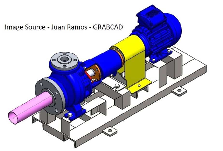
The original Model Creator of the above image is Mr. Augusto Brozoski. You can check his YouTube video to learn how to draw this model.
How does Centrifugal Pump Work?
The working principle of the pump is the conversion of energy. Refer to the chart that makes this entire energy conversion process easier to understand.
Below is a schematic diagram of the centrifugal pump that explains step by step working of the pump.
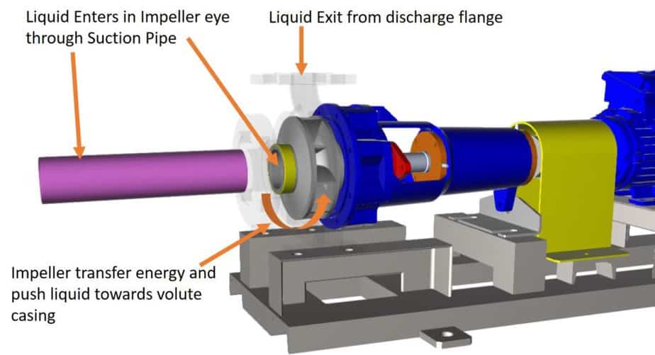
- Liquid enters the pump suction nozzle.
- It enters inside the rotating impeller vane through the eye. – Impeller gets its energy from the driver (Motor, Engine, or Turbine)
- The rotating impeller forces liquid outward by centrifugal force. The liquid will get velocity and pressure during this process.
- Now, liquid enters inside the volute casing (sometimes with a diffuser), which reduces its velocity and further increases the pressure. It also directs fluid towards the discharge nozzle.
- You can check the animation below for the fluid movement from suction to discharge of the pump.
- The impeller and casing are the main parts that do all the work of the conversion of energy. The impeller transfers the power to fluid, and the casing helps to convert the same liquid head.
Centrifugal Pump Quiz – Test yourself, Take This Quiz
Unlock New Skills with Our Best Selling Online Courses
Factors That Impact Centrifugal Pump Working
Suction Pressure – If pressure at pump suction is less than required, it may lead to cavitation. Cavitation will severely impact pump performance and can damage the impeller permanently.
Flow at suction – Constant flow of fluid is required at pump suction; otherwise, it will not operate at the design condition. If flow reduces at suction, discharge flow will get reduced accordingly. If there is no flow at suction, it will seriously damage pump internals. You cannot dry run this type of pump. Furthermore, you must prime the pump before you start if it empties after the last use.
Viscosity of the fluid – Centrifugal pumps are an excellent choice for a clean and low viscous fluid. Usually, liquid with less than 500 Centistoke is the right choice. However, you can design a pump to hand more viscous fluid, but that be more power hungry and inefficient.
Vapor Pressure of the Fluid – Process fluid will very low vapor pressure is not suitable as it may lead to cavitation. If you are working with such liquid, make sure you have enough pressure in your system all the time.
Density of the fluid – Liquid with high density will not work with the pump. With higher density, a pump must do more work to push the liquid. Again, this will create less than ideal situations for operation and maintenance due to increased power and maintenance requirements.
Centrifugal Pump Types
Before discussing the types of centrifugal pumps, I will show you how a pump, in general, is classified to understand the whole concept of these types of pumps easily. Refer to the chart below;
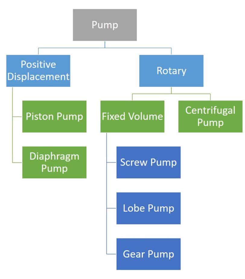
The chart above broadly classified pumps into two categories rotary and positive displacement. Under positive displacement, piston type and diaphragm type pumps are widely used.
Under rotary type, you can further classify pumps into fixed volume pumps such as gear and lobe and centrifugal pumps.
There are multiple ways to classify the centrifugal pump. Refer to the chart given below;
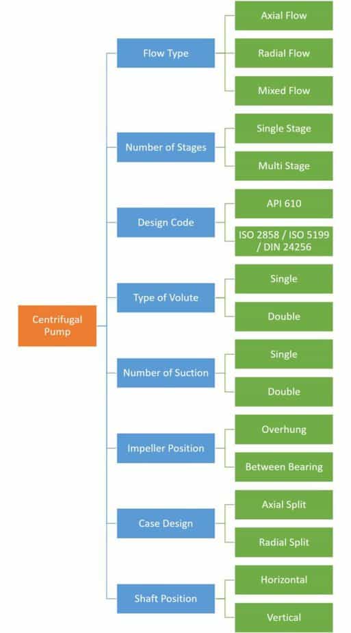
Different Types of centrifugal pumps are used in industries based on the requirement. They are classified based on design code, impeller types & numbers, application, etc. The charts above cover the most common way to organize these pumps. The same pump can be a part of two or more groups.
Depending on flow type: Radial, Axial, and Mixed Flow Types Centrifugal Pump
You can see Radial, Axial, and Mixed flow types designs in the image below.
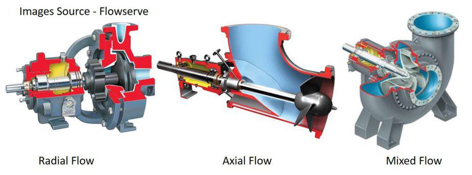
Radial Flow Pump
In radial flow, fluid take a 90-degree turn from the suction. Most centrifugal pump comes under this category. Fluid enters through the horizontal suction flange and leaves through a vertical discharge flange. That means discharge is perpendicular to the pump shaft. This design is used when you want to increase discharge pressure with a limited flow of the fluid. You can simply say that it is high pressure – low flow rate pump. Most pumps used in oil and gas will fall into this category.
Axial Flow Pump
When the fluid flows parallel to the pump shaft, it is called an axial flow pump. In this type of pump, pumping liquid moves parallel to the pump shaft. This action resembles working or propellant. This pump is useful when handling a large amount of fluid with very little pressure head. Dewatering pumps and water circulation pumps are everyday use cases of axial flow pumps.
Unlock New Skills with Our Best Selling Online Courses
Mixed Flow Pump
As the name suggests, when the fluid flow is mixed of both radial and axial, it is called a mixed flow pump. It is a tradeoff between radial and axial type pumps. It can handle a high flow rate with a decent increase in pressure head.
Number of stages
Depending on the requirement, two or more impellers can be used in the pump. The image below shows the single-stage pump with a single impeller on the shaft and the multiple-stage pump with many impellers on the same shaft.
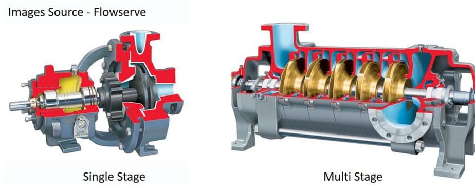
A single impeller design is useful for a large flow rate with relatively less increase in the pressure head. The multistage design is used when you need a very high head at discharge. In this case, impellers are connected in the series so that each stage will boost the fluid pressure.
Use of Design Code
When it comes to using code for pump design, the following two are used in most cases.
- API 610 – This is most widely used in oil and gas, petrochemical, and similar process industries. It has its own pump classification.
- ISO 5199 / ISO 2858 / DIN 24256 – DIN 24256 is now merged with ISO 2858. These standards are used for all types of pump design.
Unlock New Skills with Our Best Selling Online Courses
Type of Volute Casing
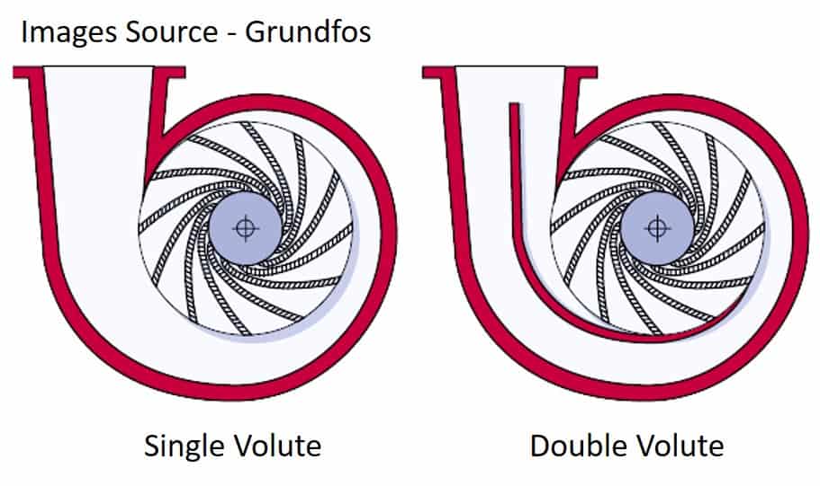
Pump casing can be of the single volute type or double volute type, as shown in the image below. The most pump you will see inside the refinery will be of a single volute type. Double volute has an advantage over the single. It will minimize the shaft defection when the pump operates outside the BEP (Best Efficiency Point).
Case Design
Radial Split – Radially split pump casing opens perpendicular to the shaft axis and parallel to the impeller.
Axial Split – In this design, the pump casing is spliced into two halves that get separated horizontally, or you can say that parallel to the shaft axis.
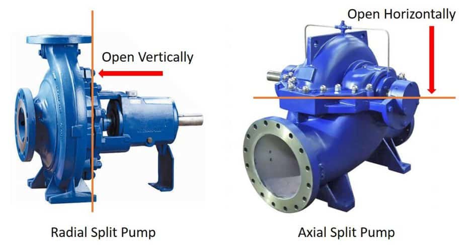
It sounds difficult to understand, but just look at the image, and you will immediately know what I am trying to explain. It is the way you open a pump for any maintenance.
Vertical or Horizontal Shaft Position
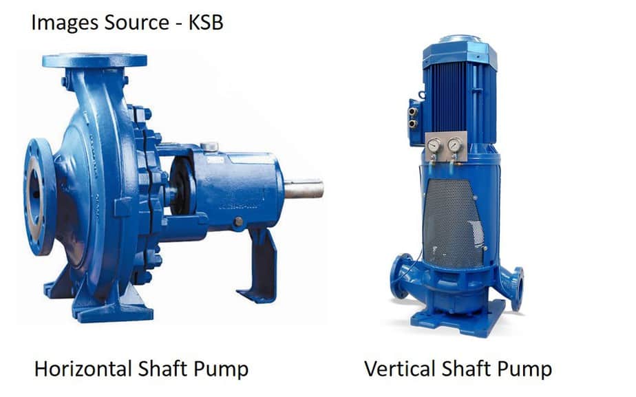
In the case of a vertical pump, the pump’s shaft is in a vertical direction, and the pump is usually installed in the sump. This type of pump is used in a limited space. Pump in borewell and sump collection are some examples of this type.
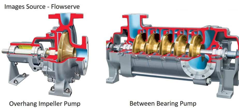
Horizontal pumps are more widely used as it is easy to maintain. In this type, a shaft is a horizontal plane. The impeller can be overhung or between bearing types. The image shows both types.
Unlock New Skills with Our Best Selling Online Courses
Number of Suctions
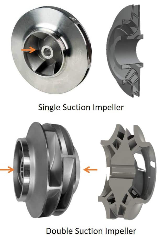
Most centrifugal pump has a single suction design. However, single-suction will not be enough when the flow rate is very high. In this case, double suction pumps are used. The impeller of this type of pump is designed in such a way that fluid enters from both sides as compared to a single side in a normal case.
Don’t get confused with the name, even in the double suction pump; you have single suction and discharge flange. It is the design of the impeller and casing that are different.
The image below shows single and double suction centrifugal pumps and impellers.
Depending on Impeller Position
Overhung – In this type of pump, the impeller is supported through a single bearing. The impeller is attached at the end of the shaft. This design facilitates both horizontal and vertical installation of the pump.
Between Bearing – In this type, the impeller is installed on the shaft, and the shaft is supported by bearings at both ends. Horizontally installed multistage pumps come in this design.
Refer to the image given below for an example of these types.
Learn more about API 610 Centrifugal Pump Types.
Reference for Images
- Flowserve – https://www.flowserve.com/en/products/pumps
- Ruhrpumpen – https://www.ruhrpumpen.com/en/products
- Sundyne – https://www.delta-p.no/products/api-610-pumps/
Are You Piping Components Master?
