Pipe support selection is an integral part of piping design. Proper support is essential to avoid vibration, sagging, nozzle damage, excessive stress, etc., in the pipeline.
In this article, you will learn about different types of support as listed below and some of the selection criteria.
- Shoe Support
- Saddle Support
- Clamp support
- U-bolt Support
- Cardel / Wear Pad
- Trunnion / Dummy Support
- Spring Support
- Hanger Support
- Pipe Guide
- Limit Stop / Line Stop
- Anchor
- Special Pipe Supports
Let’s start with data requirements. To select the proper support, you need the following information;
Why is Pipe Support required?
ASME B31.3 provides the purpose of the pipe support. You can check the list below;
- Keep the stress within acceptable limits.
- Prevent leakage from the joints due to vibration or uneven settlements
- Prevent Excessive thrust and moments on the connected equipment (such as pumps and turbines)
- Good support prevents excessive stresses in the supporting (or restraining) elements.
- Avoid Resonance with imposed fluid-induced vibrations
- Maintain good thermal flexibility in pipeline
- Keep pipeline in position
- Prevent sagging and distortion
- Prevent excessive heat flow to keep supporting elements’ temperature within their design limits.
Piping shall be adequately supported, anchored, or guided to prevent undue stresses, deflection, and excessive vibration. This will help protect both piping and connected equipment from excessive loadings due to thermal, weight, steelwork deflections, wind, earthquake, etc.
Piping cannot be supported bare on the top of structural steel to avoid corrosion between a pipe and structural steel.
All pipes should therefore be supported on pipe shoes. Pipe sizes with a Nominal Diameter of 40 (1½”) and below in certain pipe classes can be isolated from the structural steel using a 10mm thick insulated pad with a U-bolt. This will be determined during detailed design (based on the Pipe Specification provided by the Client).
Pipe shoes are normally shop welded where possible. Supports are typically designed for the hydro-test condition (pipeline full of water), except in those cases when the specific gravity of the flowing medium is more than water. In such cases, the actual operating load shall apply.
Documents required for Support Design
- Piping support standard.
- Line list with details such as pipe sizes, construction material, insulation thickness, operating temperatures, pressure, hydro / air testing, etc.
- Piping General Arrangement drawings, structural drawings,
- List of Valves and Speciality items with weight
- List of equipment connections
Once you have all the required information, you can move ahead with selecting pipe support.
While designing the support, keep Constructability in mind. Here are some Commandments that help you achieve the desired support system.
- Keep It Straight and Simple
- Keep Its Structures Simple
- Keep Its Specification Simple
- Keep It Shop Standard
- Keep Its Standard Simple
- Keep It the Same Size
- Keep It Square and Squatty
- Keep Its Support Simple
- Keep Its Schedule Sacred
- Keep it Site Suitable
P&ID Quiz – Test yourself, Take This Quiz
Unlock New Skills with Our Best Selling Online Courses
Types of Pipe Support and Function
There are several ways to classify pipe supports. All different design of the support falls into some of these categories. Here, you can see some of the most used terms associated with supporting the pipeline.
Standard Pipe Supports
This term defines the types of support used with all types of pipelines in the plant. They are standard in design and manufactured in bulk. Only the size of the support changes with the size of the pipelines. No independent design calculation is required for this type of support. You can select this support for the standard support catalog used across the project. Let’s see some of them.
Shoe Support
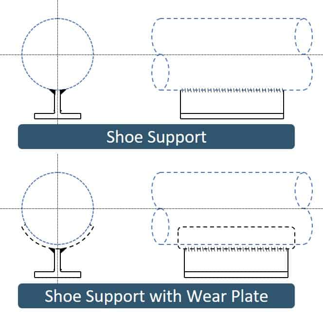
It is fabricated support that is directly welded to a pipe’s underside, which rests on the supporting structure. Usually, an I- beam cut into two halves is used as a shoe. The height of the shoe depends on the thickness of the insulation.
It allows the pipe to move in axial and transverse directions but only restricts vertical downward movement. It is also used to reduce wear from sliding for lines subject to movement.
Saddle Support
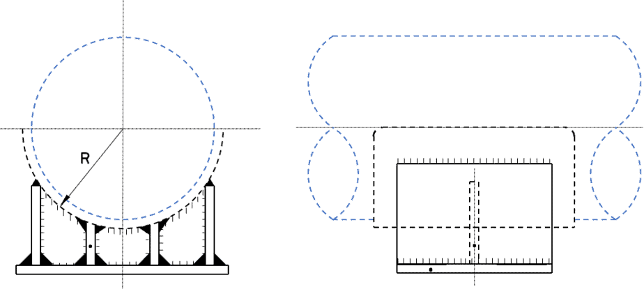
This type of support supports large diameter pipes that cannot be directly rested on the pipe rack. It is a shop fabricated shoe, as shown in the image below. A base plate with the same material grade as the pipe (Reinforcement pad) is used to welding this support with the mother pipe.
Clamp support
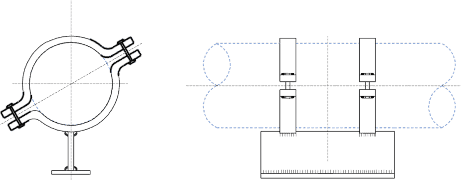
Different types of clamps are used to support both vertical and horizontal lines. It is also used to support Non- metallic piping. In the image below, you can see the clamp type shoe support. Non-metallic or metallic thin plate (Lining plate) is used to avoid direct pipe contact with a clamp.
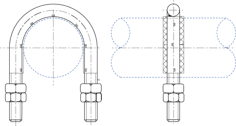
U-bolt Support
It is one of the most used support types for a non-insulated pipeline. A U-shaped bar with both ends threaded is put around the pipe, and nuts are used to fix it with the structural beam. These supports can be used as guiding points.
Unlock New Skills with Our Best Selling Online Courses
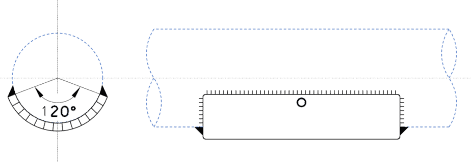
Cardel / Wear Pad
It is a simple plate with completable metallurgy that is directly welded with a pipe. It is used to protect the pipe from wear due to the sliding movement of the pipeline.
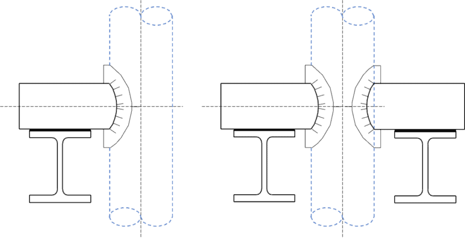
Trunnion / Dummy Support
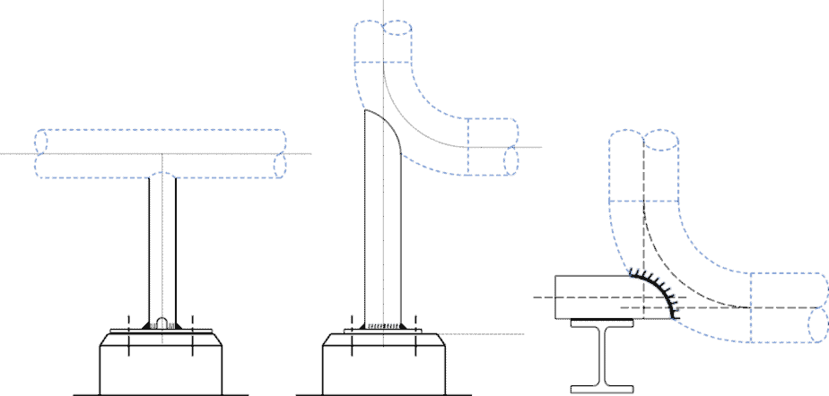
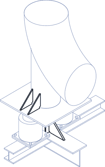
A trunnion is a dummy pipe branch directly welded to the main pipe, as shown below. The other end of the branch is rested on the secondary support. It is used to support both horizontal and vertical lines.
It can also be welded to the elbow to support the line in both vertical and horizontal directions, as shown in the image below.
Spring Support
Thermal expansion or vibration in the system can disturb the pipe’s resting and may move up or down. Therefore, any rigid support on such a line tends to lift up and remain inactive during operating conditions. In such a case, flexible support (springs) is provided, which can take the load in all operating and cold conditions.
Due to spring elements in this type of support, which can get compressed or released depending upon the load, can provide constant support to the pipe. Spring support can either be resting or hanger type, as shown here.
The spring vendor typically supplies the units with all associated rods, turnbuckles, beam attachments, clamps, pins, etc.
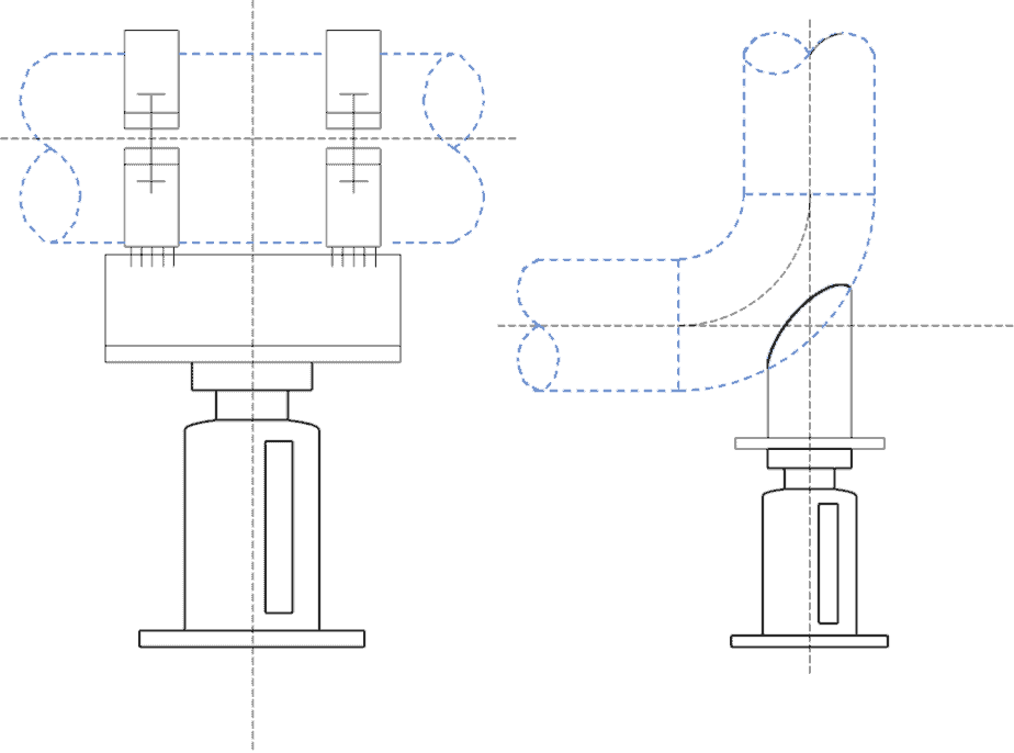
Two types of spring support are used in piping: constant load and variable load.
- Constant load Spring Support: As the name suggests, there is no change in the load applied to the pipe due to thermal expansion over the complete range of movement. It is used where large movement is expected.
- Variable load Spring Support: In this type, a load applied by support on the pipe changes as the spring moves through its range depending on the spring constant. This type of support is used where large movement is not expected.
Hanger Support
This type of spring support is suspended from the structure or concrete beam. It can be rigid, variable, or constant spring support. A clevis, U-bolt, or pipe clamp connects support with a pipe. The support height can be adjusted with the help of a turnbuckle or by adjusting the spring.

Pipe Guide
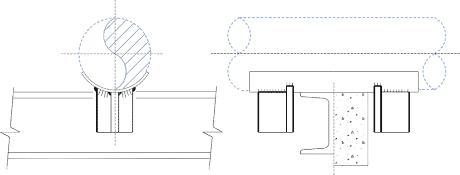
The function of the guide is to allow pipe movement in a predetermined direction. This is a means of allowing a pipe to move along its length but not sideways. Guides are necessary for the proper functioning of expansion joints. It helps in maintaining the alignment of the pipeline. The guide is also used to restrict the vertical movement of the pipe. Here, in the image, you can see both types of guides.

Limit Stop / Line Stop
A line stop is used to prevent excessive line travel on the Piperack. It will contain a pipe from moving along its length. This is the opposite of to guide that allows free axial movement.
Anchor
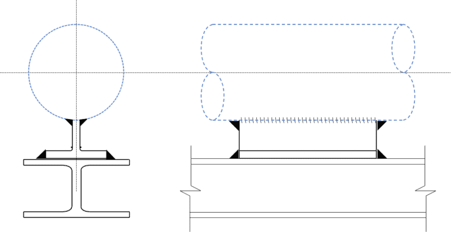
As the name suggests, an anchor restricts all three types of movement in the pipeline at a given point. An anchor aims to divide a pipeline into individual expanding sections. Anchor design should consider all kinds of loads that may occur in the pipeline to withstand any condition that arises during operation.
Unlock New Skills with Our Best Selling Online Courses
Special Pipe Supports
As the name suggests, this type of support is designed on a case-to-case basis. A separate drawing is issued based on the calculation to fabricate this type of support. On critical lines of a reactor, compressor, etc., these supports are used. Here, you can see the sample of the SPS.
What is the difference between Primary and Secondary Pipe Support?
When support is directly welded/attached to the pipeline, it is called primary support. Pipe shoes, clamps, trunnions, wear pads, etc., are examples of primary support. Secondary supports are those on which primary support rest. For example, steel structures, civil foundations, sleepers, and racks are secondary support. Refer to the image below to see the difference.
How are Pipe Supports shown in the Drawing?
The pipe supports are typically indicated on isometrics as a “PIPE SUPPORT CALL OUT”. The “PIPE SUPPORT CALL OUT” consists of letters and numbers combination, giving the type of support to be welded. Refer below
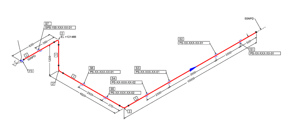
Support for a pipe at a location can be a combination of standard support types or special pipe support. These indications shall be written as separate items. For example, a pipe support frame that supports multiple pipes is indicated only on one piping isometric drawing. For all other lines, reference is made to the piping isometric drawing with the “PIPE SUPPORT CALL OUT” indication.
Special pipe supports are indicated on the piping isometric. All components, including support standard items, will be listed on the individual special pipe support drawing. No support components will be listed on the piping isometric. A Special pipe support is mentioned as SPS, where SPS – means Special Pipe Support.
Recommended Spans and Guide Spacing for Pipe Support
The span between the two support depends on load, size, the temperature of the fluid, and pipeline material. Guides support vertical pipes. The following needs to be considered while calculating the span.
- Small bore lines required more frequent support to avoid sagging.
- Liquid lines need more frequent support than gas-filled lines.
- The span of hotlines is shorter than cold lines of the same size and thickness.
- Insulated lines require a shorter span due to the weight of the insulation.
- Space requirements of equipment at grade can sometimes influence pipe rack bent spacing.
- The spacing between supports is selected such that the maximum deflection does not exceed the design requirement.
Refer to the table below with a normally good pipe support span for different materials. Again, these requirements vary from company to company.
| Maximum Recommended Pipe Support Spans | |||
|---|---|---|---|
| Carbon Steel, Galvanized Carbon Steel, Stainless Steel and Duplex | |||
| Pipe Size (DN) | Max Span (M) | Pipe Size (DN) | Max Span (M) |
| 20 | 2 | 200 & 250 | 8 |
| 25 | 3 | 300 | 9 |
| 40 & 50 | 4 | 350 & 400 | 10 |
| 80 | 5 | 450 to 550 | 11 |
| 100 | 6 | 600 | 12 |
| 150 | 7 | 650 to 1050 | 12 |
| CuNi and GRE | |||
| 50 & 80 | 3 | ||
| 20 | 2 | 100 | 4 |
| 25 | 3 | 150 & 200 | 5 |
| 40 | 3 | 250 to 600 | 6 |
| In process units, common pipe racks and major facilities the maximum spacing for pipe supports is 6m normally. For pipes DN 42 (NPS – 24”) size and smaller, the spacing between supports are selected such that the maximum deflection does not exceed 16 mm (5/8″). | |||
Guides are provided at regular intervals to maintain proper pipe alignment on the pipe rack. In the table below, you can see the general practice for placing guides along the line.
| Maximum Recommended Guide Spacing | |||
|---|---|---|---|
| Carbon Steel, Galvanized Carbon Steel, Stainless Steel and Duplex | |||
| Pipe Size (DN) | Max Span (M) | Pipe Size (DN) | Max Span (M) |
| 20 | 2 | 50 to 150 | 6 |
| 25 to 40 | 3 | 200 & Above | 12 |
| CuNi and GRE | |||
| 20 | 2 | 50 to 350 | 6 |
| 25 to 40 | 3 | 400 to 600 | 6 |
Material Selection for Pipe Support
The material selection for the support and its components shall be governed by the design temperature of the line and the applicable codes. When we select the material for primary support, we must ensure that it is of compatible grade, if not the same as a pipe.
Reference
- https://inspectioneering.com/content/2019-11-12/8818/repairing-galvanized-coatings-on-structural-steel
- ASCE 7 Minimum Design Loads for Buildings and Other Structures
- ASCE Report 40262 – Wind Loads and Anchor Bolt Design for Petrochemical Facilities
- ASCE Report 40264 – Guidelines for Seismic Evaluation and Design of Petrochemical Facilities
- AISC 360 Specification for Structural Steel Buildings
- AISC 341 Seismic Provisions for Structural Steel Buildings
- AISC Manual Steel Construction Manual
- AWS D1.1/D1.1M Structural Welding Code – Steel
- ACI 318M Building Code Requirements for Structural Concrete and Commentary
- ASME B31.1 Power Piping
- ASME B31.3 Process Piping
- AS 4041 Power Piping
- ASTM A 123 Standard Specification for Zinc (Hot Dip Galvanized) Coatings on Iron and Steel Products
- SSPC SP 10 Near-White Metal Blast Cleaning (NACE NO. 2)
- SSPC SP 11 Power Tool Cleaning to Bare Metal
- MSS-SP-58 Pipe Hangers and Supports – Materials, Design, and Manufacture
- Nirmal Surendran Menon, “Pipe Support Design Considerations for Hydrocarbon Facilities”, International Journal of Science and Research (IJSR), https://www.ijsr.net/search_index_results_paperid.php?id=ART20195078 , Volume 8 Issue 2, February 2019, 406 – 409
Co-Author with Mr. Nirmal Surendran Menon
Are You Piping Components Master?
