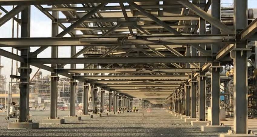
In this article, I am going to talk about Pipe Rack design. Many factors influenced the design of pipe racks in the Oil and gas process facility. You can see some of them below;
- Availability of space
- Number of interconnected Units
- Number of pipelines and sizes (loads)
- Future space requirement
Each Piperack is unique. Civil / Structural engineers are responsible for the overall design. However, multiple engineering disciplines work together to finalize a design. Let’s see what documents are required before you start working on the Pipe Rack design.
Documents Required for Pipe rack Design
- Overall Plot Plan – This will provide the layout detail of the Piperack
- Unit Plot Plan – Provides unit level layout, height, width, and length data
- Equipment Layout – This will help to provide branching detail from the rack
- PFD (Process Flow Diagram) – Provides connection details between equipment
- P&ID (Piping and Instrumentation Diagram) – Provides line size, valves, and process data
- Line List – Provide the list of all lines in the units and process facility
- Design code and Standard – Gives the technical requirements for design
- Fire-Proofing Information
- Electrical and Instrument Cable Tray details – These data are needed for space calculation.

Who Designs What?
As said earlier, Piperack design is a multi-disciplinary job. Therefore, here in the table below, I have tried to summarize the role and responsibility of various engineering teams.
| Activity | Performer Team | User Team |
|---|---|---|
| Piperack Dimension (Width, Height, and length) | Piping Engineering | Civil and Structural Engineering |
| Pipe and equipment load calculation | Piping Engineering | Civil and Structural Engineering |
| Electrical and Instrument Cable Tray calculation | Electrical and Instrument | Civil and Structural Engineer, Piping Engineering |
| Fireproofing | Technical HSE and Fire | Civil and Structural Engineer, Piping Engineering |
| Foundation Calculation | Civil Engineering | |
| Piperack structural design. Selection of structural member sizes considering various loads such as wind, earthquake, live load, etc. | Structural Engineer | Civil and Piping Engineering |
Design Considerations
Structural steel – The design of all structural steel must conform in accordance with AISC 360 Specification & AISC 341 Seismic Provision. Hot rolled “W” steel sections shall be ASTM A992, while for angles, channels, plates, and bars shall be ASTM A36 according to ASTM Specifications.
| ASTM Steel Properties | W steel sections | Channel/Angles/Plates |
| Steel Grade | ASTM A992 | ASTM A36 |
| Minimum Yield Stress, fY | 350 MPa | 250 MPa |
| Tensile Strength, fu | 400 MPa | 400 MPa |
- Modulus of elasticity Es = 200 x 103 N/mm2
- Density of steel r = 78.5 KN/m3
- Poisson’s ratio n = 0.25
- Coefficient of thermal expansion = 12 x 10-6/oC
It must be noted that all Structural steel members shall be hot dipped galvanized for corrosion prevention.
P&ID Quiz – Test yourself, Take This Quiz
Unlock New Skills with Our Best Selling Online Courses
Structural Bolts and Nuts – High-strength bolts for structural steel connections should conform to ASTM A325 specification and be hot dipped galvanized to protect against corrosion.
As per ASTM A325, shear strength in bearing type, Fnv, where threads are not excluded from shear planes = 330 N/mm². Where threads are excluded from shear planes = 414 N/mm². Tension strength, Fnt 620 N/mm².
All bolted connections that are part of a Seismic Load Resisting System (SLRS) must be fully pre-tensioned to meet requirements for the slip-critical connection.
Minimum Pretension is equal to 0.70 times the minimum tensile strength of bolts, rounded off to nearest KN, as specified in ASTM specifications for A325M and A490M bolts with UNC threads.
| A325M | Bolt Minimum Pretension, KN |
| M20 | 142 KN |
| M22 | 176 KN |
| M24 | 205 KN |
| M27 | 267 KN |
| M30 | 326 KN |
| M36 | 475 KN |
Welds – All welding must conform to AWS D1.1 and AISC 360 Specification & AISC 341 Seismic Provision.
- Nominal tensile strength for filler metal = 480 N/mm²
- Nominal shear strength (LRFD) = 0.6 x 480 = 288 N/mm²
- Nominal shear strength (ASD) = 0.3 x 480 = 144 N/mm²
Minimum welds shall be 6mm fillet and as far as possible site welding shall be minimized.
Anchor Bolts – Anchor bolts, as the name suggests, helps in anchoring the structural steel columns of the Pipe Rack(s) to the concrete foundation. In general, all anchor bolts for structural steelwork & equipment’s are carbon steel anchor bolts. It shall be ASTM A36/F568M Class 4.6 for temperatures not significantly above normal atmospheric temperatures. In addition, anchor bolts shall be hot dipped galvanized.
| ASTM A36 /F568M Class 4.6 bolts | Load |
| Allowable yield strength, fy | 250 N/mm² |
| Allowable tensile strength, fut | 400 N/mm² |
Unlock New Skills with Our Best Selling Online Courses
Types of Loads for Pipe rack Design Calculation
Basic “Load Cases” used in Pipe Rack design are as follows
- LOAD 1 – Dead Load DL
- LOAD 2 – Pipe Empty Load EE
- LOAD 3 – Pipe Operating Load EO
- LOAD 4 – Pipe Anchor Logitudinal Load (X dir) ALX
- LOAD 5 – Pipe Anchor Transversal Load (Z dir) ALZ
- LOAD 6 – Pipe Surge Load (X dir) SLX
- LOAD 7 – Pipe Surge Load (Z dir) SLZ
- LOAD 8 – Pipe Friction / Thermal Load FL
- LOAD 9 – Pipe Hydrotest Load (HL)
- LOAD 10 – Live Load (LL)
- LOAD 11 – Wind Load on Frames (X dir)
- LOAD 12 – Wind Load on Frames (Z dir)
- LOAD 13 – Wind Load on Pipes (X dir)
- LOAD 14 – Wind Load on Pipes (Z dir)
- LOAD 15 – Total Empty Gravity Load (EGL = DL + EE)
- LOAD 16 – Total Operating Gravity Load (OGL = DL + EO)
- LOAD 17 – Total Hydrotest Gravity Load (HGL = DL + HL)
- LOAD 18 – Notional Load Empty (X dir)
- LOAD 19 – Notional Load Empty (Z dir)
- LOAD 20 – Notional Load Operating (X dir)
- LOAD 21 – Notional Load Operating (Z dir)
- LOAD 22 – Notional Load Hydrotest (X dir)
- LOAD 23 – Notional Load Hydrotest (Z dir)
- LOAD 24 – Seismic Load Empty (X dir)
- LOAD 25 – Seismic Load Empty (Z dir)
- LOAD 26 – Seismic Load Operating (X dir)
- LOAD 27 – Seismic Load Operating (Z dir)
Wind Load – Wind Load should be in accordance with ASCE 7-05 and ASCE Report #40262 “Wind loads for Petrochemical Facilities”.
Seismic Load – Seismic Load shall be in accordance with ASCE 7-05 and ASCE Report #40264 “Guidelines for Seismic Evaluation and Design of Petrochemical Facilities”.
Foundations – Site soil conditions will dictate the foundation type to be used. The project design specifications usually state foundation design parameters based on a site geotechnical investigation report. Typically, independent spread footings or pile caps are used at each column.
Co-Author with Mr. Nirmal Surendran Menon
Are You Piping Components Master?


